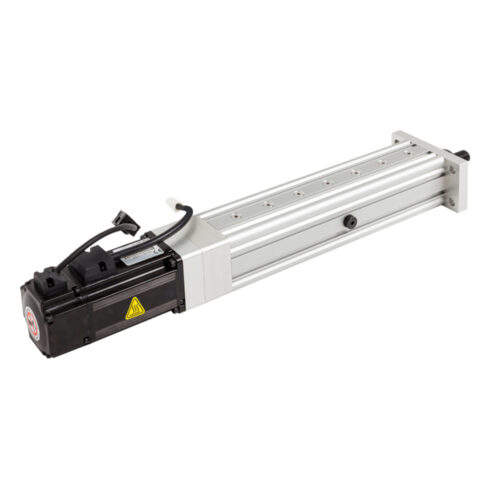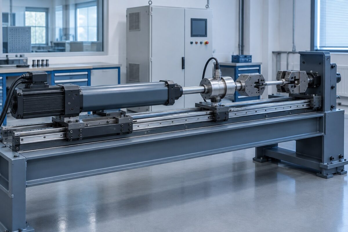
A servo electric cylinder can suit a component or endurance test rig when the test requires programmable axial motion or loading within a verified force-speed-duty envelope. Selection starts with the approved test method—not the actuator catalogue. Define the waveform, specimen load path, independent measurement, fixture stiffness, cycle count and safe fault response before choosing a cylinder.
1. Define what the test must prove
Separate static tension or compression, production-step verification, cyclic endurance and fatigue testing. Each creates a different motion and thermal duty. ZwickRoell lists electromechanical testing actuators for tensile, compression, component, production-step and long-stroke fatigue tests, but the complete test machine determines measurement quality.
Write down the controlled variable, measured result, acceptance window and stopping rule. A commanded actuator position is not automatically specimen displacement, and motor current is not automatically calibrated force.
2. Convert the method into a load and motion envelope
- Minimum and maximum force in both directions
- Stroke, velocity, acceleration and dwell
- Waveform and reversal frequency
- Cycles per test, tests per shift and target life
- Moving mass, gravity direction and disturbances
Peak force alone is inadequate. Bosch Rexroth’s selection guidance emphasizes changing forces, static versus dynamic load, duty cycle and the total motion cycle. Tolomatic application examples likewise define stroke, speed, load range, profile and test rate.
3. Separate actuation from measurement
Use the actuator encoder for motion control, but define independent references where the test method requires them. A typical system may include a calibrated load cell in the specimen force path, an external displacement sensor at the method’s datum, synchronized acquisition and a documented zero procedure.
Decide sample rate, filtering, synchronization, calibration and raw-data retention. See the NEFEIT guide to servo electric cylinder data acquisition.
4. Design the fixture and load path
Keep the specimen, joints, load cell and actuator on the intended axis. Fixture deflection, backlash and joint movement can distort the result. Side load, eccentric load and overturning moment should be carried by an external guide or frame rather than the cylinder rod.
Confirm mounting, articulation, travel limits, service access and behavior if a specimen breaks. The testing and simulation application guide provides the broader system context.
5. Validate duty, temperature and life
Endurance work can create more demanding reversal and thermal conditions than occasional positioning. Review RMS load, screw speed, acceleration, lubrication, bearing and screw life, motor and drive temperature, and cooling time. Use a force-speed-time profile rather than combining unrelated catalogue maxima. Start with the servo electric cylinder selection guide.
6. Define safety and acceptance before ordering
Specify guarding, overtravel protection, emergency-stop behavior, mechanical retention, overload response and the safe state after power or sensor loss. The machine builder must complete the applicable risk assessment; an actuator alone does not establish machine safety.
Agree acceptance tests for unloaded motion, loaded performance, measurement correlation, temperature rise and repeat cycles. Record the configuration, software, sensor identities and calibration status so the test can be repeated.
Test-rig RFQ checklist
- Test method and specimen drawing
- Force-versus-position or force-versus-time envelope
- Stroke, speed, acceleration, waveform and frequency
- Fixture and external-guidance drawing
- Sensors, calibration and data-acquisition requirements
- Cycle count, daily schedule and target life
- Installation space, environment and utilities
- Controller, communication and safe-state requirements
Review the available servo electric cylinder architectures, then send the complete test envelope for an application-specific configuration review. Final performance must be confirmed for the selected actuator, fixtures, sensors and control system.
Engineering references
- ZwickRoell electromechanical servo testing actuators
- Bosch Rexroth selection steps
- Tolomatic construction-material test mechanism
- Tolomatic power-drill life testing