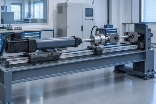
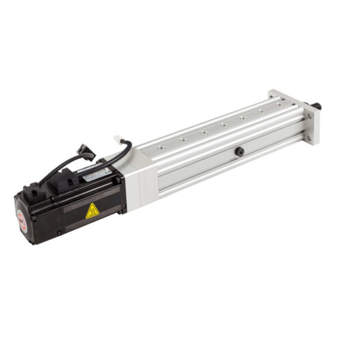
A servo electric cylinder should primarily provide axial thrust. If the tooling, carriage or workpiece creates lateral force or overturning moment, use external linear guides to carry those loads and keep the cylinder rod aligned with the direction of travel.
This distinction matters early in machine design. An actuator can meet the required thrust and stroke on paper, yet still experience binding, accelerated wear or inconsistent motion when the load path is offset from the rod axis. The solution is not simply to choose a larger cylinder. It is to design a guided mechanism in which each component has a clear job.
Illustrative application concept, not a customer installation. Final guidance, coupling, guarding and actuator selection depend on the machine design.
What side load means for an electric cylinder
The intended working force of a rod-style electric cylinder acts along its extension and retraction axis. Side load acts perpendicular to that axis. It may come from the weight of tooling, an offset work point, a carriage that is not independently supported, or a fixture that forces the rod out of alignment.
Thomson explains that side loading can misalign actuator components and lead to rubbing, binding, premature wear or damage. Bosch Rexroth similarly recommends external guidance for heavy lateral loads and notes that misalignment can shorten actuator life.
The practical rule is simple: let the cylinder push or pull along its axis; let the guide system support the carriage and resist lateral forces and moments.
Where unintended side load comes from
Side load is often created by the surrounding machine, not by the actuator itself. Common sources include:
- Tooling whose center of gravity sits far from the rod axis.
- A vertical load supported directly by the extended rod.
- Long adapters or overhung brackets that create a bending moment.
- Rails and cylinder mounts that are not parallel.
- A rigid coupling that forces two imperfectly aligned systems together.
- A workpiece or fixture that shifts during pressing or clamping.
- Frame deflection under peak force.
A rod-end bearing or clevis can accommodate limited angular movement in an appropriate joint, but it does not turn the cylinder into a linear guide. The complete mechanism must still control translation and rotation as required by the application.
What a guided layout should do
A robust guided layout normally separates the load path into two functions:
- The servo electric cylinder supplies axial force and commanded motion. Its rod connects to the moving member along the travel axis.
- Linear rails and bearings support the moving carriage. They carry lateral load and resist pitch, yaw and roll moments according to their rated arrangement.
The machine base must be stiff enough to hold the cylinder and guide references in alignment under load. Rail spacing, bearing spacing and carriage geometry should be selected from the actual force direction, center-of-gravity offset, moment load and travel. These are guide-system calculations, not values that should be inferred from the cylinder thrust rating.
NEFEIT shows this separation in its automotive bearing press-fit application: guidance controls the moving structure while the electric cylinder supplies axial thrust. The exact arrangement must still be engineered for the customer machine.
Alignment and coupling checks
External rails only help if the cylinder is installed without forcing misalignment into the assembly. During design and commissioning, check the following:
- The guide travel axis and cylinder rod axis are parallel through the full stroke.
- The connection point stays close to the intended force line.
- Mounting faces are flat, rigid and referenced from controlled datums.
- The coupling or joint accommodates only the intended degrees of freedom.
- The carriage moves freely before the rod is connected.
- The completed assembly moves freely through the full stroke before production loading.
- Cable carriers, hoses, covers and stops do not pull the carriage sideways.
- Thermal growth and frame deflection are considered where they may change alignment.
Do not use the cylinder to pull a misaligned carriage into position during assembly. If connecting the rod changes the carriage motion or requires force, correct the geometry first.
What external guidance does not replace
Guidance is essential for lateral-load management, but it does not complete actuator selection by itself. The cylinder still has to be checked against the full operating cycle, including axial load, stroke, speed, acceleration, deceleration, dwell time, cycles per minute, mounting orientation and environment.
The NEFEIT servo electric cylinder selection guide explains the broader input set. The choice between an inline or folded-back layout is another packaging decision; neither arrangement eliminates the need for proper external guidance when the machine produces side load.
Also remember that machine guarding, risk assessment, stopping behavior and controls belong to the complete machine design. An application illustration is not a released engineering drawing or safety validation.
RFQ checklist for a guided electric-cylinder axis
For a model-specific review, provide more than peak thrust and stroke:
- Axial force in extension and retraction.
- Moving mass and tooling center of gravity.
- Lateral forces and moments at the carriage.
- Stroke, speed, acceleration and deceleration.
- Complete cycle profile, dwell time and cycles per minute.
- Horizontal, vertical or angled mounting orientation.
- Rail type, spacing, bearing spacing and carriage dimensions.
- Cylinder-to-carriage connection method.
- Available installation envelope and service access.
- Environment, contamination, temperature and expected maintenance conditions.
- Motor, feedback, brake and control-interface requirements.
Sharing a machine drawing or simple load-path sketch helps expose offsets and alignment constraints before a cylinder is selected.
Frequently asked questions
Can a servo electric cylinder carry any side load?
Allowable loads depend on the exact actuator, mounting, stroke position and operating conditions. Do not assume an axial thrust rating is a side-load rating. When meaningful lateral load or moment exists, use an external guide and request model-specific validation.
Does a clevis eliminate the need for linear guides?
No. A clevis can suit a pivoting connection, but it does not support a translating carriage or resist all moments. The guidance strategy must match the mechanism.
Should the cylinder or the rails be installed first?
A practical sequence is to establish and verify the guide axis, confirm free carriage motion, mount the cylinder from controlled datums, and then connect the rod without forcing alignment. The final procedure should follow the machine builder’s drawings and component instructions.
What information should I send NEFEIT?
Send the machine drawing, load and center-of-gravity location, stroke, speed, acceleration, duty cycle, mounting orientation, guide arrangement, available space and preferred motor or control interface. NEFEIT can then review a configuration within the stated conditions.
For more engineering resources, visit the NEFEIT resource center.
Planning a guided axis? Send your machine drawing, load, stroke, speed, acceleration, duty cycle and mounting arrangement for a configuration review.