
Design the pusher around the product window, not an isolated actuator speed rating.
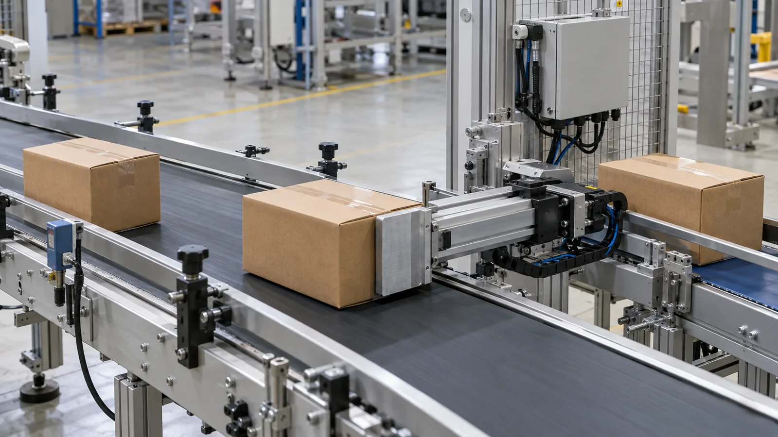
Carton sorting and lane transfer
20 kg carton; 300 mm transfer travel
0.6 m/s peak pusher velocity; 2 m/s² acceleration
Engineering feasibility study: assumed inputs and calculated values; conceptual equipment illustrations. Proposed checks require project approval and measured trials.
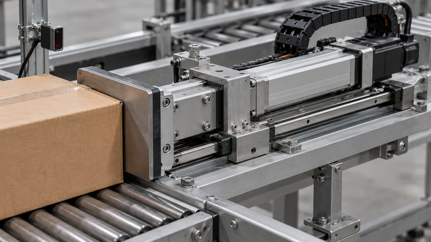
The carriage carries offset moments, with clearance for skewed cartons. A broad contact face distributes the transfer force without loading the cylinder rod sideways.
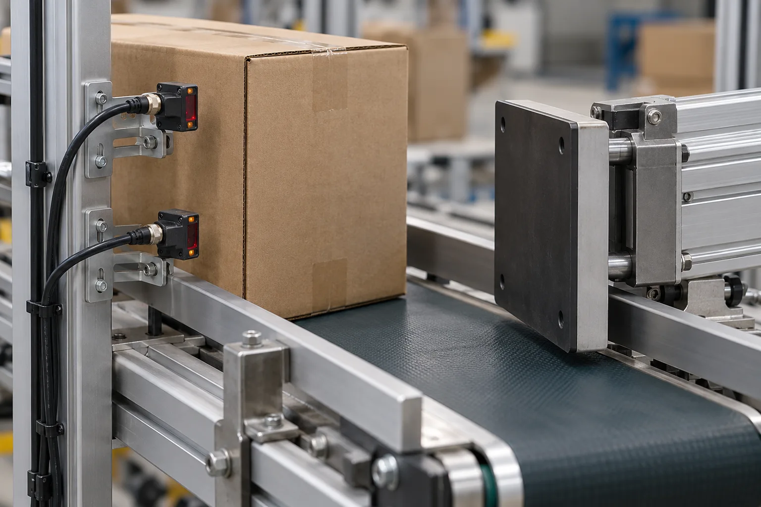
Photoeyes confirm arrival and clearance. Relate sensing latency and conveyor speed to the available transfer window, with jam detection and a controlled reset.
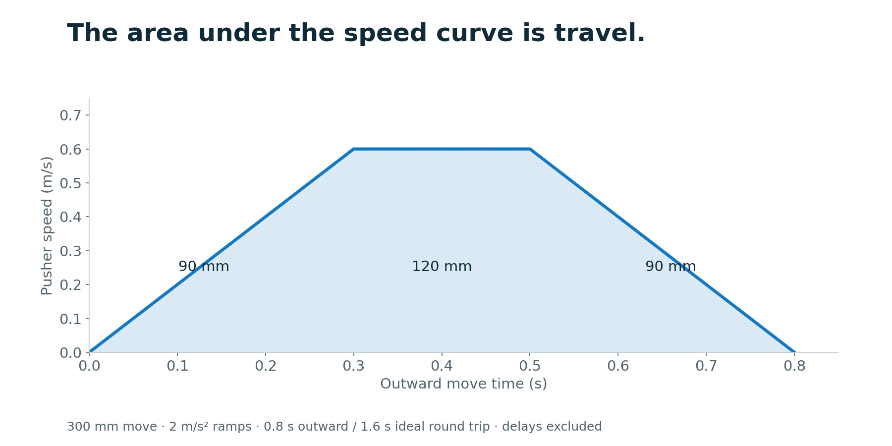
At 0.6 m/s and 2 m/s², each ramp takes 0.3 s and covers 90 mm. The remaining 120 mm takes 0.2 s: 0.8 s outward, or 1.6 s ideal round trip. Detection, dwell and conveyor delays add time. Size the total moving carriage and payload together.
Identify a qualified carton and confirm lane availability, carriage reference and line-ready conditions.
Use the line timing/encoder architecture to predict the transfer window and reject stale triggers.
Execute the product-specific profile while monitoring permitted load, travel and time.
Confirm the transfer and retract before the next approved window.
Stop the defined sequence, identify carton state and perform controlled clearance; prevent an automatic second hit on an unknown carton.
Check before resetting: Late transfer: Check trigger position, conveyor-speed reference, communication delay and the complete occupied time. Carton rotates or tips: Review contact height/area, acceleration, lane support and carton variability.
Proposed transfer trial: 100 consecutive cartons at the agreed conveyor/product window, with zero missed transfer commands or carton damage. The 1.6 s calculation excludes sensing, dwell and conveyor delays; production throughput must be measured.
Measure product detection-to-motion latency and carton arrival window at minimum/nominal/maximum conveyor speed. Verify clearance with the largest carton and worst permitted skew. Record actual outward/return times and motor temperature. Challenge missing carton, blocked guide and late arrival with an approved recovery sequence.
Record actual value, conditions, uncertainty, result and approval. Test status: planned; measured results remain to be recorded at FAT.
The useful RFQ includes line speed, carton spacing, product dimensions, receiving-lane geometry and the full transfer/return window. It should also state who owns tracking logic and product-damage acceptance. That information avoids selecting an axis from thrust and stroke alone.
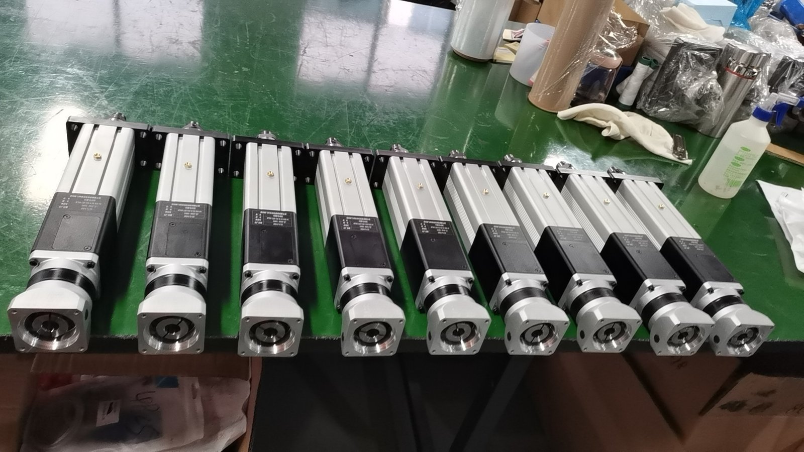
Confirm thrust versus speed, stroke, duty, mounting, motor/drive, feedback and environment together. The NFT40 photograph illustrates the product family; the study does not select that exact model.
Engineering pack: operating-cycle sizing, configuration and interface drawing, responsibility split, lubrication provisions and an agreed test plan.
Acceleration, outbound and return stroke, dwell, sensing latency and product clearance all occupy the line window. The complete sequence must fit.
Only if the qualified size, mass, strength and timing envelope supports it. Different products often require bounded profiles and controlled recipe selection.
Request the configuration-specific sizing review, interface drawing, supply boundary and proposed acceptance plan. This feasibility study contains assumed inputs and calculated values; it does not report a delivered customer project or completed FAT.
Share the drawing, load cycle and acceptance target. Start with a clear actuator scope and the engineering checks that matter to your machine.
Drawing · Load cycle · Control requirements
Drawing + operating cycle
Loads, interfaces + duty
Configuration + test plan
Agreed hardware + records