
Identify the joint by its insertion signature, then verify seating at the housing datum.
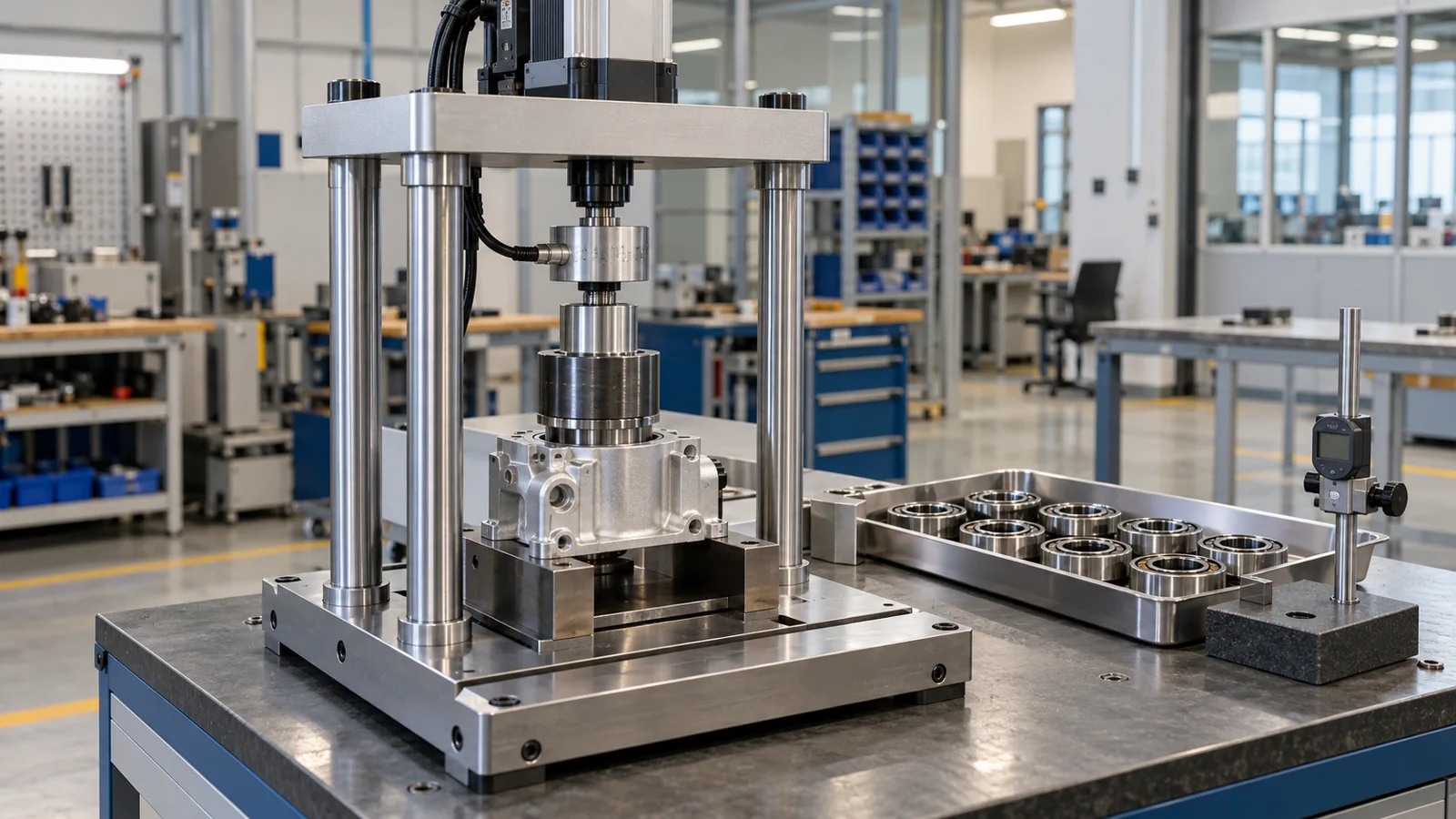
Rolling bearing into an aluminum housing; axial interference assembly
30 kN peak process thrust; 200 mm usable actuator travel
100 mm/s approach; 5 mm/s insertion; bounded dwell and controlled return
Engineering feasibility study: assumed inputs and calculated values; conceptual equipment illustrations. Proposed checks require project approval and measured trials.
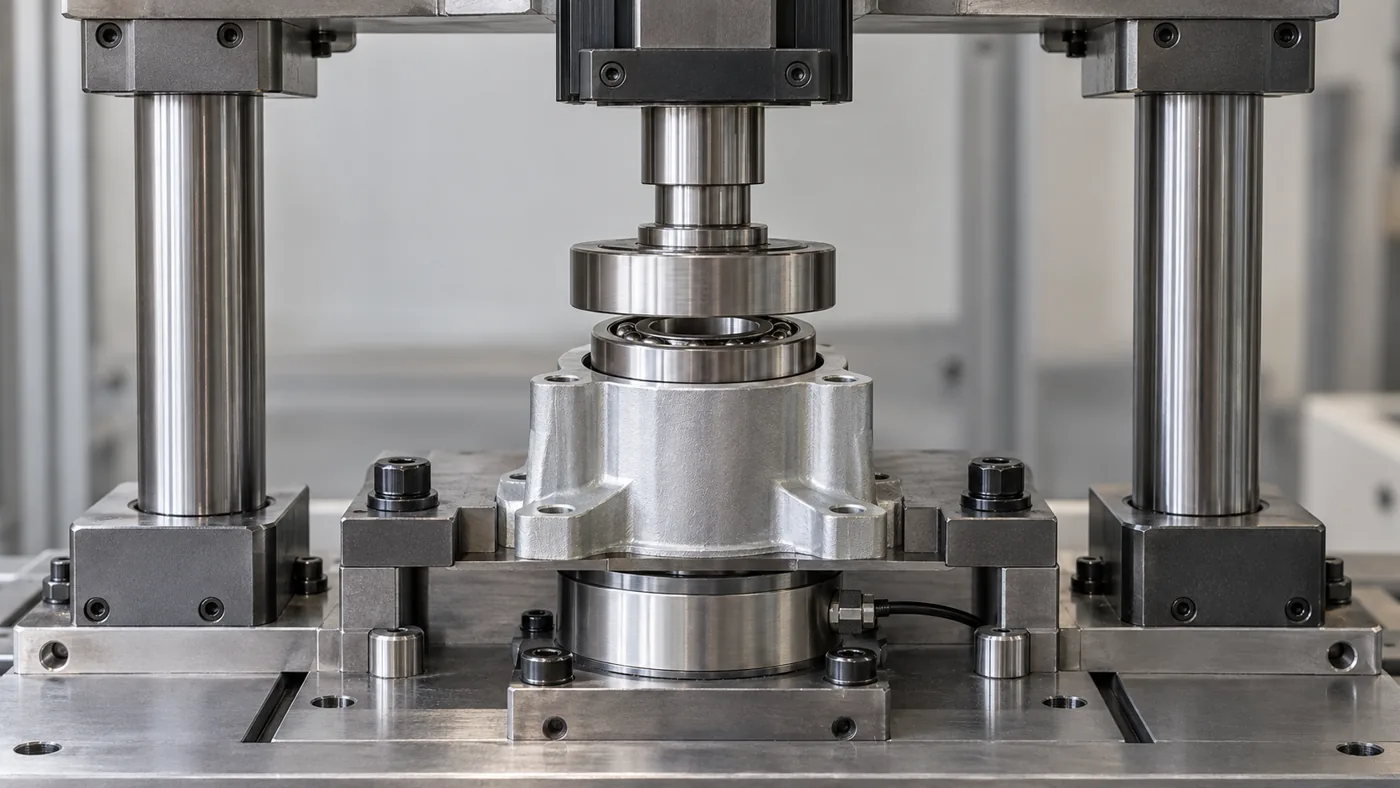
For a housing interference fit, the annular tool acts on the bearing outer ring. Support the housing close to the bore; avoid transmitting assembly force through the rolling elements.
An axial load cell and synchronized displacement identify contact, insertion and seating. Guides carry side load; the cylinder supplies axial thrust.
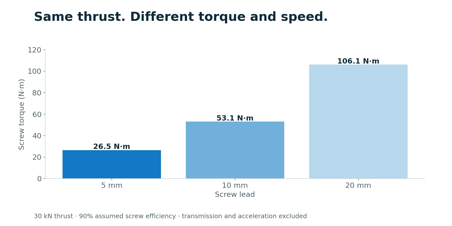
At 30 kN, 5 mm screw lead and assumed 90% efficiency, T = F × lead / (2π × efficiency) = 26.5 N·m. A 100 mm/s approach needs 1,200 screw rpm. Review acceleration, peak duration, RMS torque, screw life and buckling before selecting the motor.
Confirm part ID, fixture seating, bearing presence, sensor readiness and guarded-cycle permission.
Move to a validated clearance position; avoid striking an unexpectedly tall workpiece.
Search at controlled speed with bounded force and travel; reject contact outside the permitted region.
Capture synchronized force and displacement; terminate on qualified depth or a defined abnormal condition.
Evaluate the complete curve; mark the part pass/reject before unclamping and retain the trace.
Check before resetting: Force rises too early: Stop the cycle; check part orientation, burrs, bore contamination and tool concentricity before changing limits. Depth reached with too little force: Investigate incorrect fit, wrong part or missing component; endpoint travel alone is not acceptance.
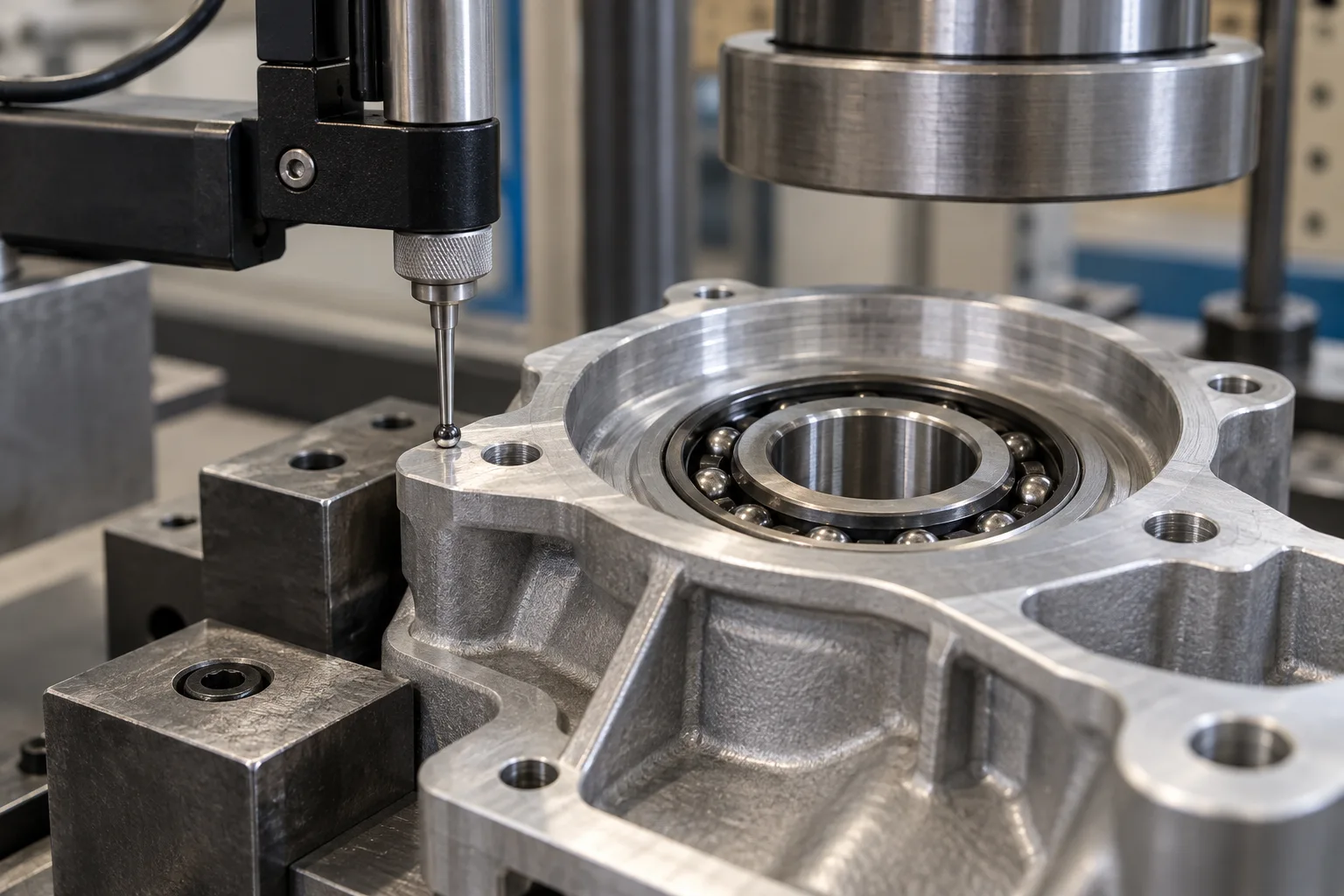
Proposed depth repeatability: ±0.05 mm over 30 qualified parts, measured from the housing datum after unloading. This is a process-development target, not a cylinder accuracy rating.
Calibrate the axial force channel at five points across the agreed working range. Record force versus independent insertion depth for 30 parts covering the approved interference-fit range. Agree the force-envelope limits from qualified assemblies before production release.
Record actual value, conditions, uncertainty, result and approval. Test status: planned; measured results remain to be recorded at FAT.
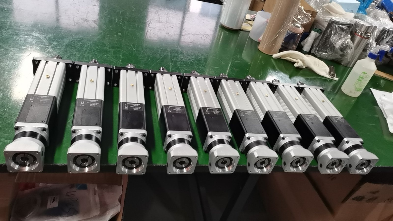
The buyer should expect a proposed actuator configuration and interface drawing, an operating-cycle sizing review, a sensor/PLC responsibility split and an acceptance checklist. A repeat order should reference the released configuration and tooling revision, rather than a loosely described “30 kN cylinder.”
Confirm thrust versus speed, stroke, duty, mounting, motor/drive, feedback and environment together. The NFT40 photograph illustrates the product family; the study does not select that exact model.
Engineering pack: operating-cycle sizing, configuration and interface drawing, responsibility split, lubrication provisions and an agreed test plan.
No. Workpiece depth also depends on frame deflection, tool compression, the datum and measurement uncertainty. Agree and verify the assembled-part tolerance under load.
Only within a validated load, travel and tooling envelope. Each component variant needs controlled tooling and its own qualified acceptance window.
Request the configuration-specific sizing review, interface drawing, supply boundary and proposed acceptance plan. This feasibility study contains assumed inputs and calculated values; it does not report a delivered customer project or completed FAT.
Share the drawing, load cycle and acceptance target. Start with a clear actuator scope and the engineering checks that matter to your machine.
Drawing · Load cycle · Control requirements
Drawing + operating cycle
Loads, interfaces + duty
Configuration + test plan
Agreed hardware + records