
In brief: Servo electric cylinder data acquisition helps engineers separate commanded motion from measured results. Define the question first, then collect synchronized signals at a useful sample rate.
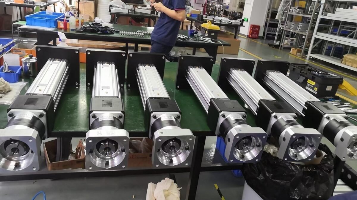
servo electric cylinder data acquisition: engineering checklist
Start with the application drawing, operating cycle and model-specific documentation. Record the baseline conditions before adjusting the machine so each test has a clear comparison. The following checks address common failure modes without assuming a universal product rating.
Choose signals that answer the question
Position command and actual position reveal tracking error. Motor current can indicate a changing load, but it is not a direct force measurement without a validated model. Add a calibrated force sensor where process force matters. Capture drive status, alarms, cycle ID and machine state.
Synchronize and label samples
Use consistent timestamps or a shared controller clock for drive, PLC and sensor data. Record units, scaling, sampling frequency and actuator model. High-frequency events can disappear in a slow trend. Set the rate based on the shortest event you need to resolve.
Protect signal quality
Route feedback and sensor wiring per the manuals. Validate zero offsets, calibration and connector integrity. Keep necessary data with appropriate access controls. Mark missing or noisy samples rather than silently interpolating them into a false fault narrative.
Turn traces into diagnosis
Compare healthy and faulty cycles at the same load and motion profile. A position error and current spike at a repeatable location may point to binding; an isolated alarm can suggest feedback or power issues. Review each inference against physical inspection. Data supports diagnosis but does not replace safety checks.
Practical verification steps
- Record the model, mounting orientation, load, stroke, speed, duty cycle and relevant alarms.
- Inspect the mechanical load path and compare measurements with the actual datasheet and drive manual.
- Change one condition at a time, log the result and retest the complete operating cycle.
- Document the final setting and hand it to maintenance and machine engineering.
Frequently asked question
What information should I send for application support? Provide the actuator model, motion profile, drawings, load and observed symptoms. This enables a more useful model-specific review than a generic force or accuracy claim.
Related resources: NEFEIT resource center, failure diagnosis and servo electric cylinder range. For an engineering review, contact NEFEIT. The THK technical resources offer background on linear guides; the installed components’ manuals govern actual limits.