
Review individual corner loads, actual deck level and independent support before selecting four lift axes.
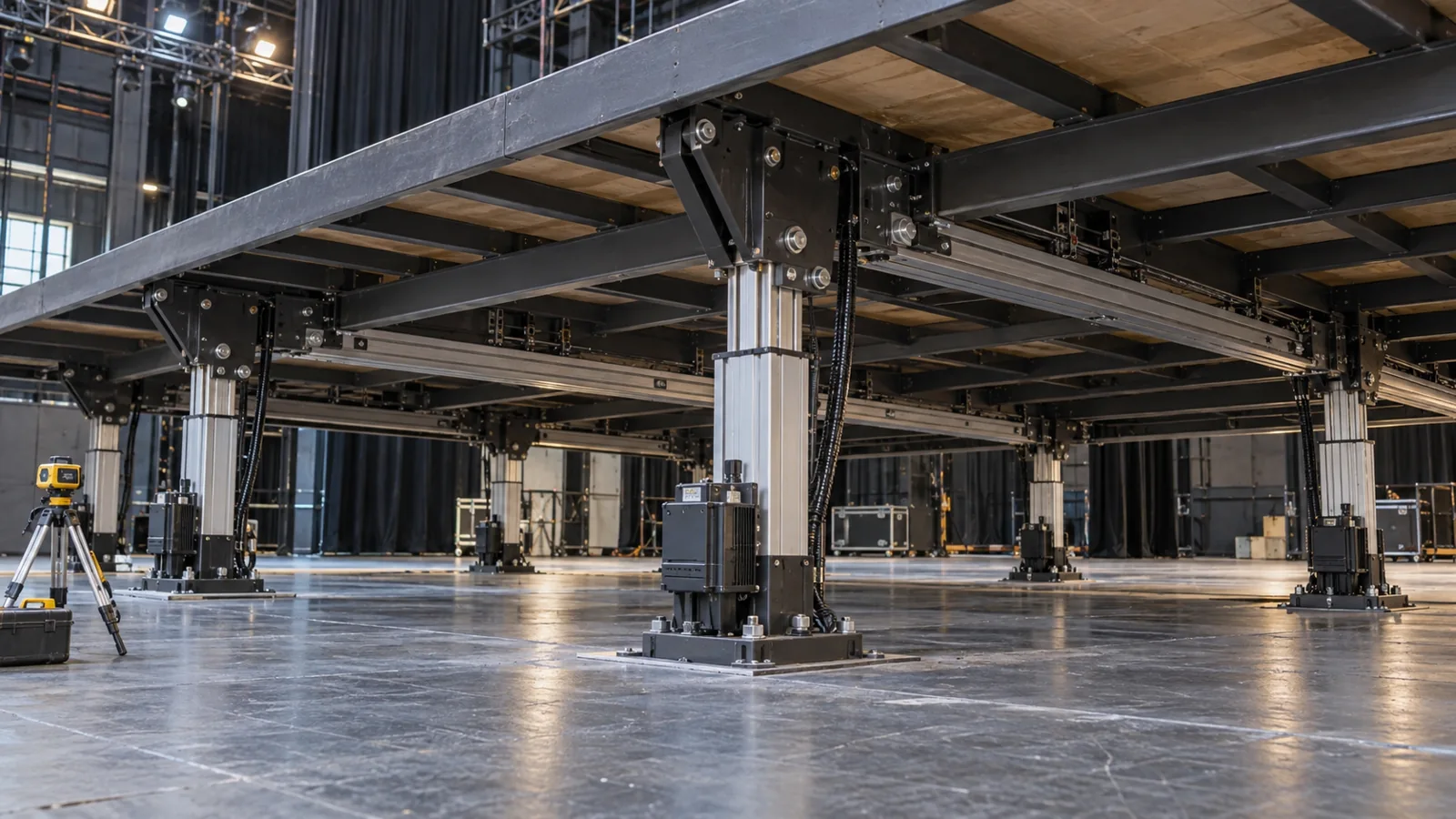
Four-point guided scenery-platform lift
1,200 kg total moving mass; 300 mm illustrative usable lift
40 mm/s lifting speed; 0.15 m/s² acceleration
Engineering feasibility study: assumed inputs and calculated values; conceptual equipment illustrations. Proposed checks require project approval and measured trials.
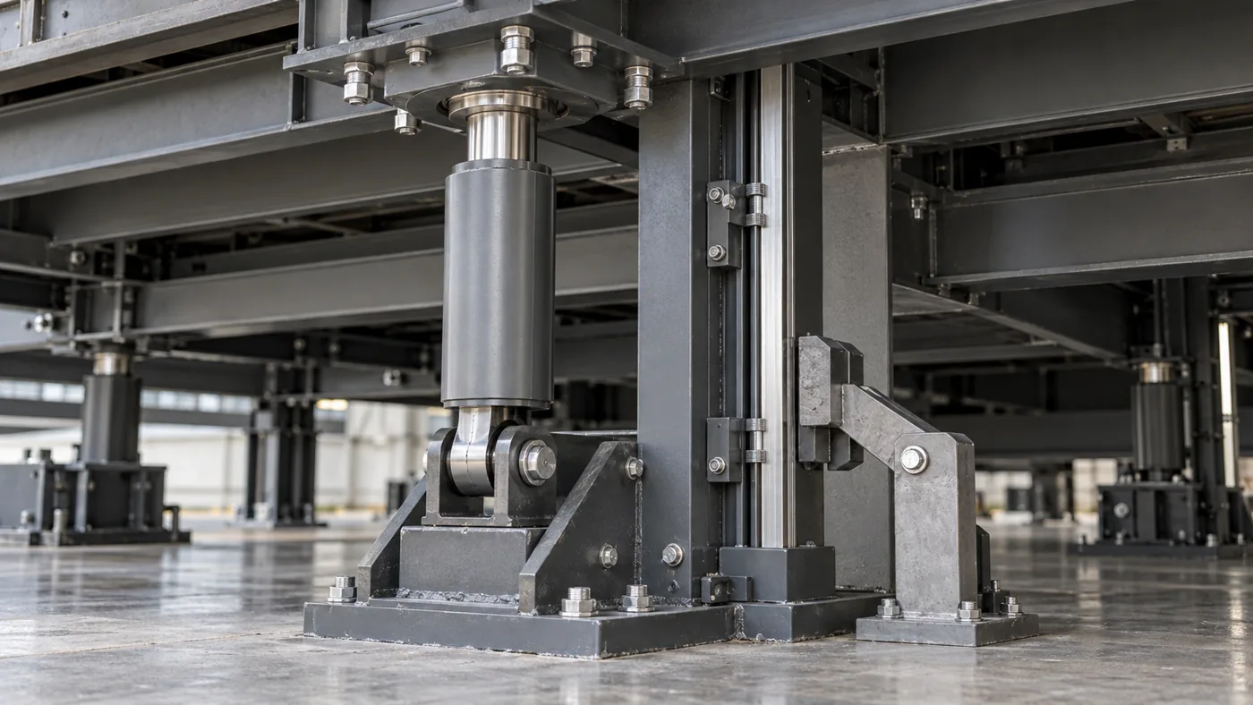
Deck structure and guide rails resist skew and overturning. Aligned cylinder joints transmit axial load; they do not substitute for platform guidance.
Independent lift-point references detect deviation. Define a coordinated stop and supported recovery if one axis lags. The integrator designs independent holding and support.
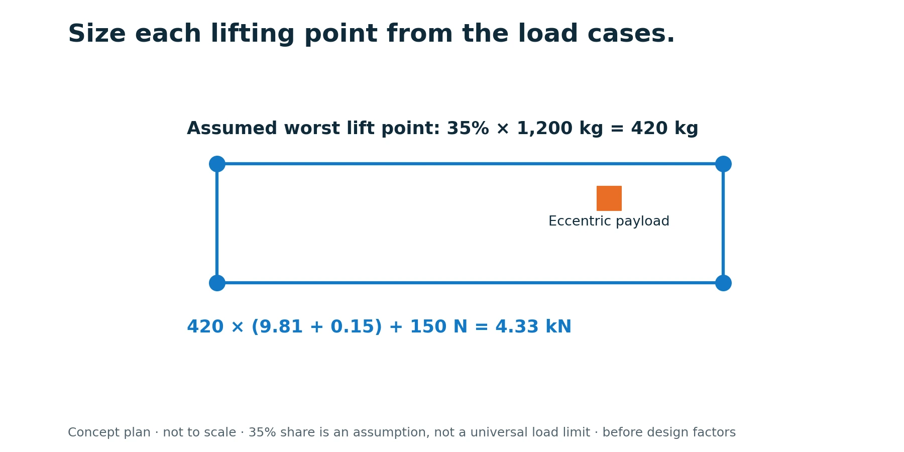
For an assumed 35% share of 1,200 kg, the corner mass is 420 kg. At 0.15 m/s² upward acceleration, with 150 N illustrative friction, force is 4.33 kN before project factors. Actual reactions require the payload map and structural analysis. A 2 mm difference across 2 m represents 0.057° tilt.
Verify the operating mode, permissible load condition, guide clearance, support status and all lift-point readiness signals.
Establish consistent lift-point references using the approved supported procedure; never force a skewed platform through a reference cycle.
Use bounded velocity, acceleration and jerk with continuous monitoring of actual lift-point deviation.
Stop according to the engineered sequence; apply the defined support/braking strategy and verify its state.
Keep the deck in a confirmed supported condition and follow the integrator’s recovery procedure; individual manual motion requires controlled authority.
Check before resetting: One lifting point lags: Review actual position feedback, drive fault, overload, guide binding and deck distortion before resuming. Drive is healthy but the deck is tilted: Inspect feedback reference, mechanical backlash/compliance and support geometry; commanded equality is insufficient.
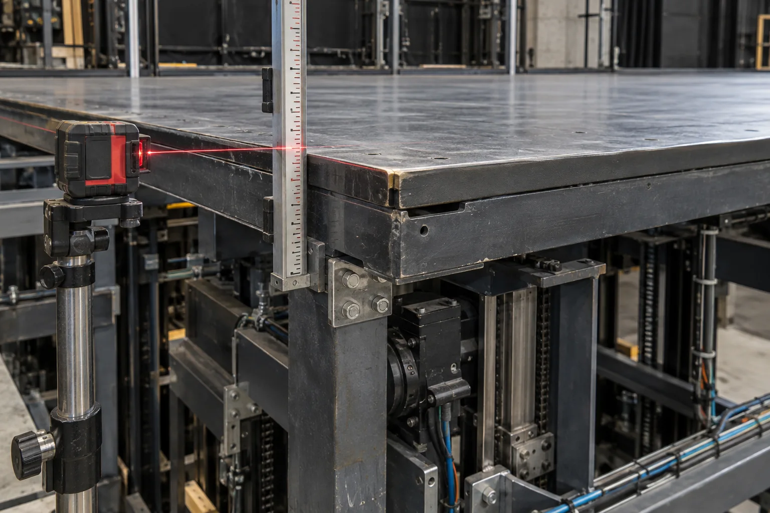
Proposed unoccupied commissioning target: corner-to-corner height difference ≤2 mm during the agreed 300 mm lift at 40 mm/s. Recheck with the specified eccentric payload. This target does not establish personnel-lifting suitability.
Weigh the complete moving assembly and map reactions for every payload position. Measure all four corners with independent displacement references. Log position difference throughout acceleration, constant speed and stopping. Determine fault thresholds and stopping distance through the machine risk assessment; verify support/holding behavior with an approved unloaded procedure first.
Record actual value, conditions, uncertainty, result and approval. Test status: planned; measured results remain to be recorded at FAT.
The procurement discussion should cover installed depth, point-load calculations, cylinder interfaces, feedback architecture, control ownership and independent support. A quotation for four actuators is not a quotation for a qualified stage lift; the released scope must make that distinction explicit.
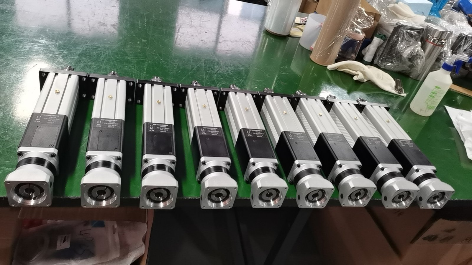
Confirm thrust versus speed, stroke, duty, mounting, motor/drive, feedback and environment together. The NFT40 photograph illustrates the product family; the study does not select that exact model.
Engineering pack: operating-cycle sizing, configuration and interface drawing, responsibility split, lubrication provisions and an agreed test plan.
They measure their own drive motion. Whether this is sufficient depends on the mechanics, required accuracy and fault analysis; actual lift-point or platform feedback may be required.
Stage operation introduces changing payload positions, coordinated multi-point motion and potentially occupied use. These affect load cases, control response, support and validation of the whole machine.
Request the configuration-specific sizing review, interface drawing, supply boundary and proposed acceptance plan. This feasibility study contains assumed inputs and calculated values; it does not report a delivered customer project or completed FAT.
Share the drawing, load cycle and acceptance target. Start with a clear actuator scope and the engineering checks that matter to your machine.
Drawing · Load cycle · Control requirements
Drawing + operating cycle
Loads, interfaces + duty
Configuration + test plan
Agreed hardware + records