
Resolve a small process force, limit contact energy and support the board directly beneath the connector.
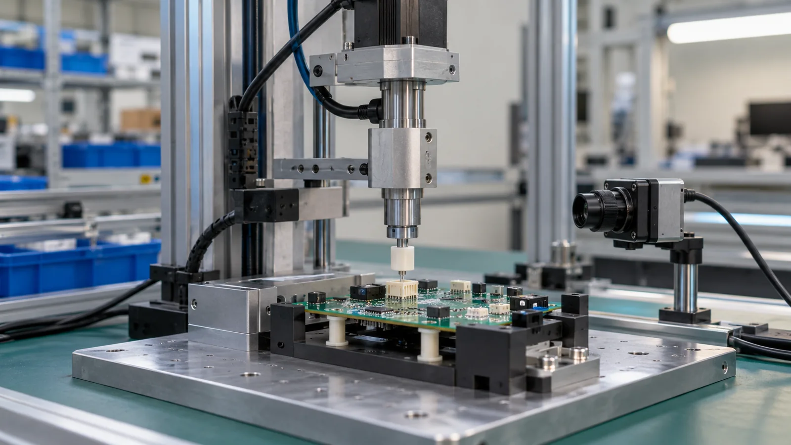
Connector seating on a supported PCB
80 N target process force; 50 mm illustrative actuator travel
40 mm/s approach; 1 mm/s controlled contact/seat phase
Engineering feasibility study: assumed inputs and calculated values; conceptual equipment illustrations. Proposed checks require project approval and measured trials.
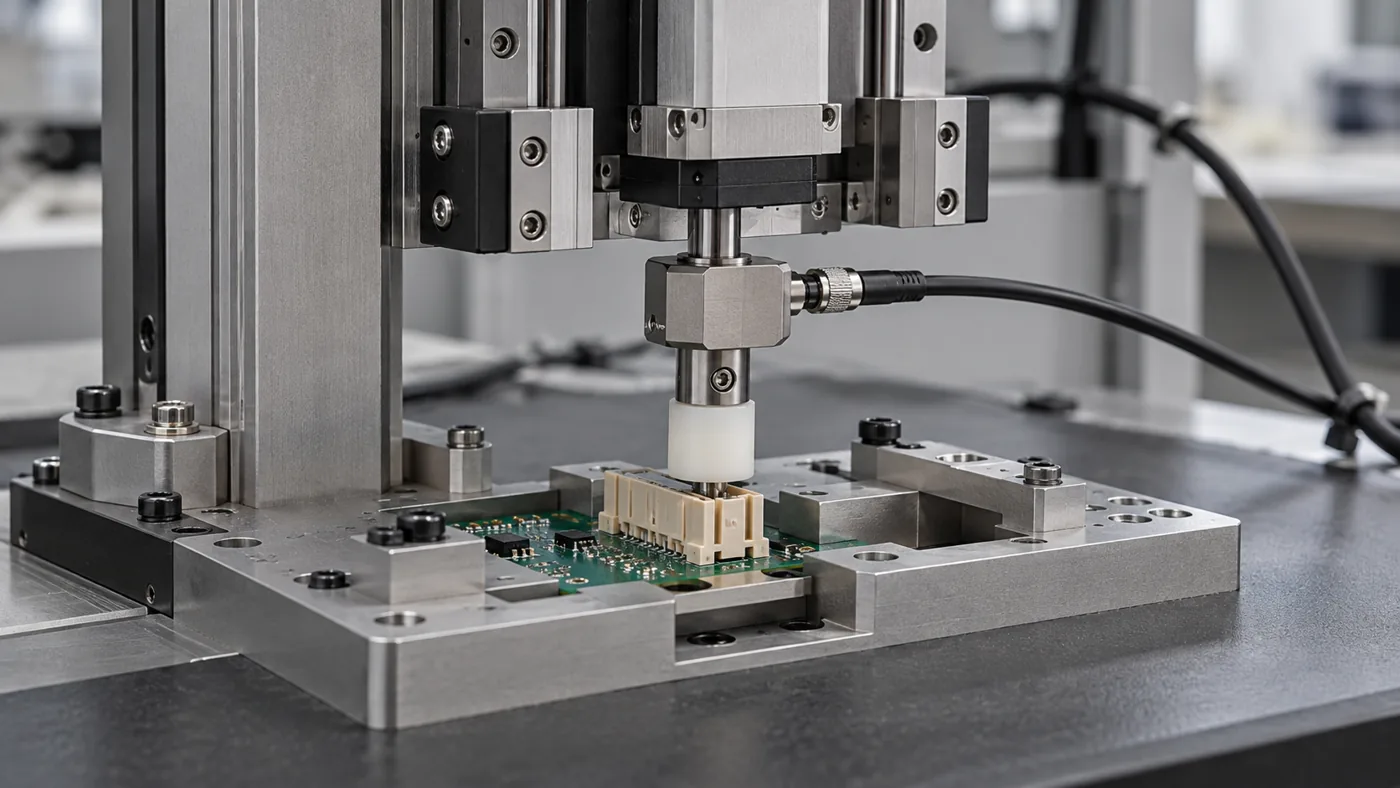
Place support beneath the insertion region while clearing underside components. The approved connector surface determines tip geometry and alignment.
Mount a suitably ranged axial sensor above the tool. Characterize intended compliance, noise and overload protection rather than relying on motor current alone.
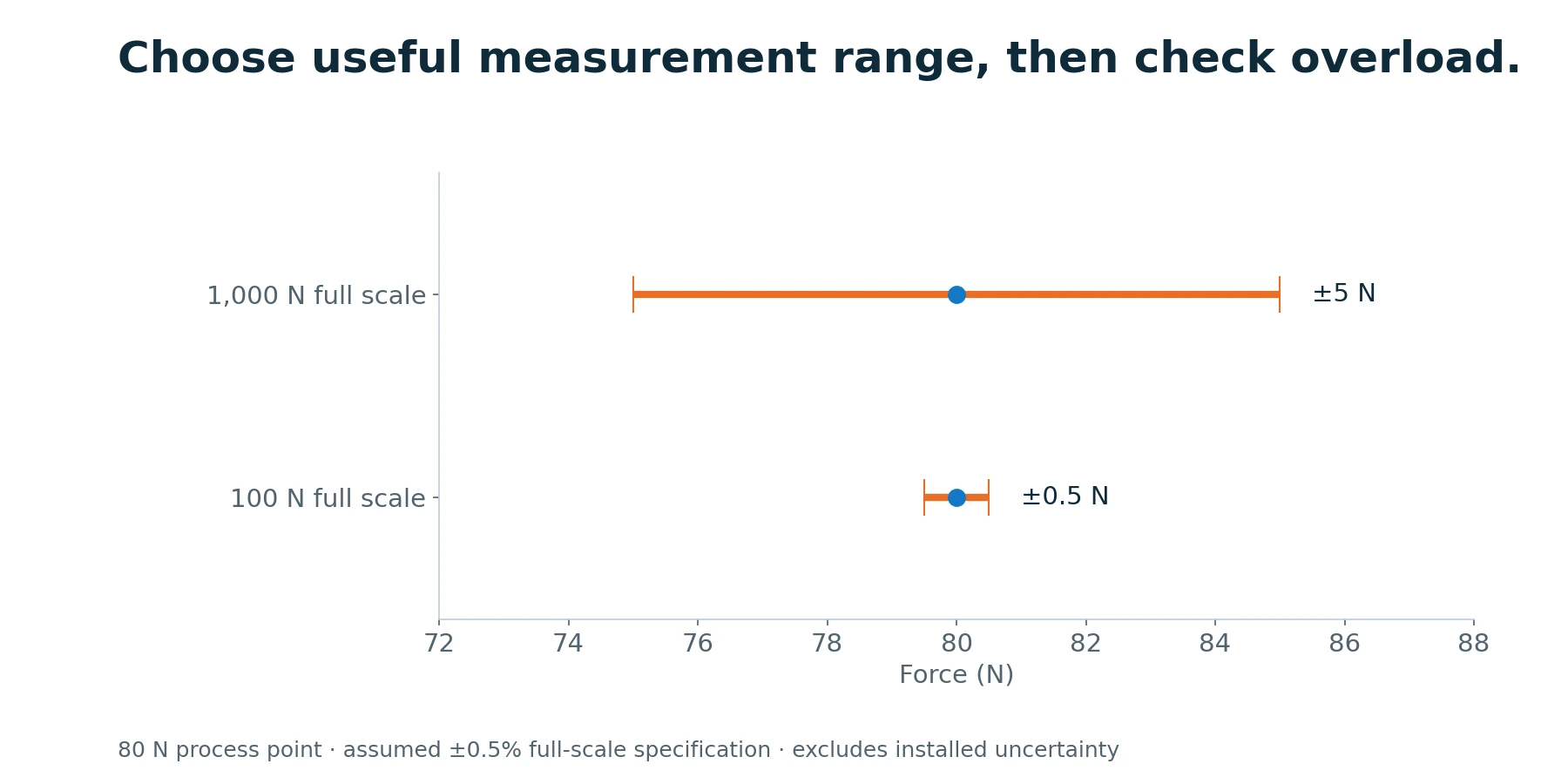
An assumed ±0.5% full-scale specification gives ±5 N on a 1,000 N sensor and ±0.5 N on a 100 N sensor. At 80 N, range matters. Check credible overload and the installed uncertainty from calibration, electronics, zero drift, filtering and alignment before selecting the sensor.
Verify board orientation, connector presence, nest seating and the approved recipe.
Move to a validated pre-contact position; check for unexpected tall components.
Advance slowly within bounded force/travel/time limits and confirm the contact region.
Execute the qualified force/depth method without exceeding component limits; record contact and final measurements.
Unload, retract and apply the specified visual/electrical or dimensional inspection before declaring acceptance.
Check before resetting: Contact force is noisy: Check sensor range, grounding/shielding, mechanical vibration, filtering and motion acceleration. Depth looks correct but the connector is damaged: Review the actual pressing surface, board support, peak dynamic load and the component inspection method.
Proposed measurement budget: total installed force uncertainty ≤±1 N around the 80 N process point, with verified overload protection. Sensor full-scale error alone does not prove this budget. Seating-depth tolerance follows the connector drawing.
Calibrate the assembled force chain around the process point; include zero drift, amplifier noise, mounting effects and repeatability. Verify board support beneath the contact point. Record 30 representative insertions, then inspect connector engagement and PCB condition with the agreed method.
Record actual value, conditions, uncertainty, result and approval. Test status: planned; measured results remain to be recorded at FAT.
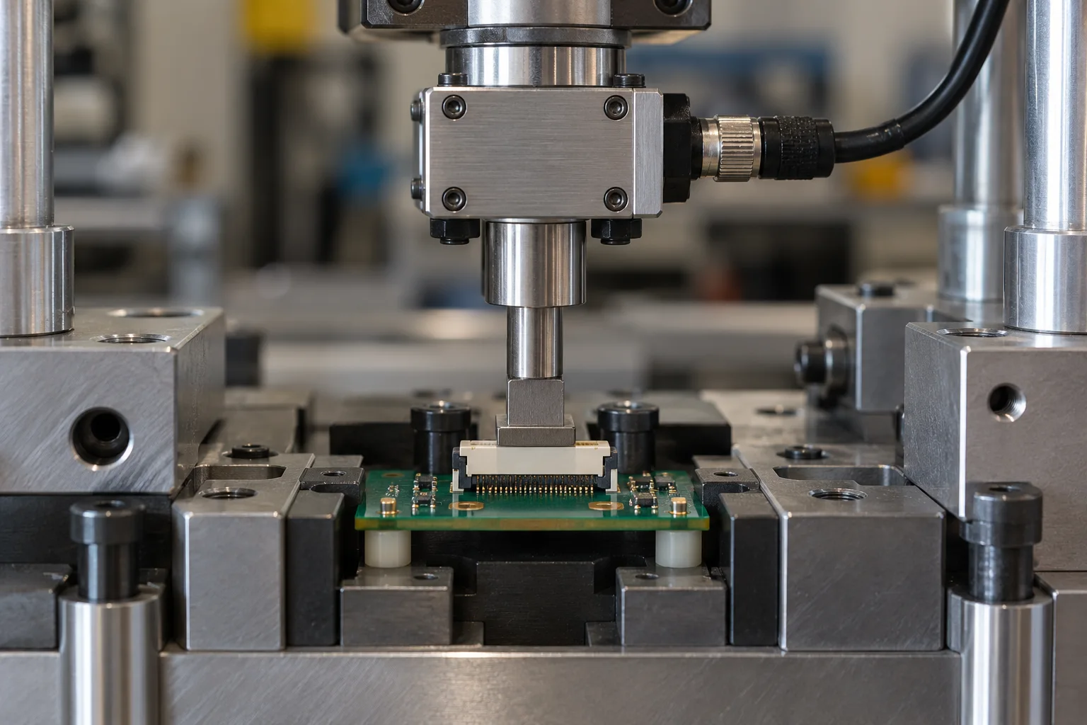
Ask the supplier to demonstrate the usable low-force operating range with the proposed motor, sensor and tooling—not just quote positioning resolution. The RFQ should include component limits, board layout, support constraints and the required product inspection method.
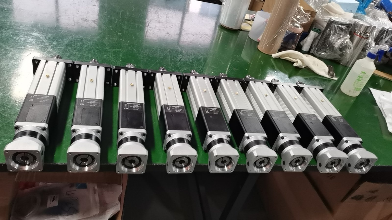
Confirm thrust versus speed, stroke, duty, mounting, motor/drive, feedback and environment together. The NFT40 photograph illustrates the product family; the study does not select that exact model.
Engineering pack: operating-cycle sizing, configuration and interface drawing, responsibility split, lubrication provisions and an agreed test plan.
No. The contact datum, board bending, tool compliance, measurement noise and loaded behavior determine the assembled result.
No. Lubricants, wear particles, materials, covers, exhaust/airflow and the complete station require review and qualification against the specified cleanliness requirement.
Request the configuration-specific sizing review, interface drawing, supply boundary and proposed acceptance plan. This feasibility study contains assumed inputs and calculated values; it does not report a delivered customer project or completed FAT.
Share the drawing, load cycle and acceptance target. Start with a clear actuator scope and the engineering checks that matter to your machine.
Drawing · Load cycle · Control requirements
Drawing + operating cycle
Loads, interfaces + duty
Configuration + test plan
Agreed hardware + records