
Turn the test waveform into speed, acceleration and duty requirements, with independently measured response.
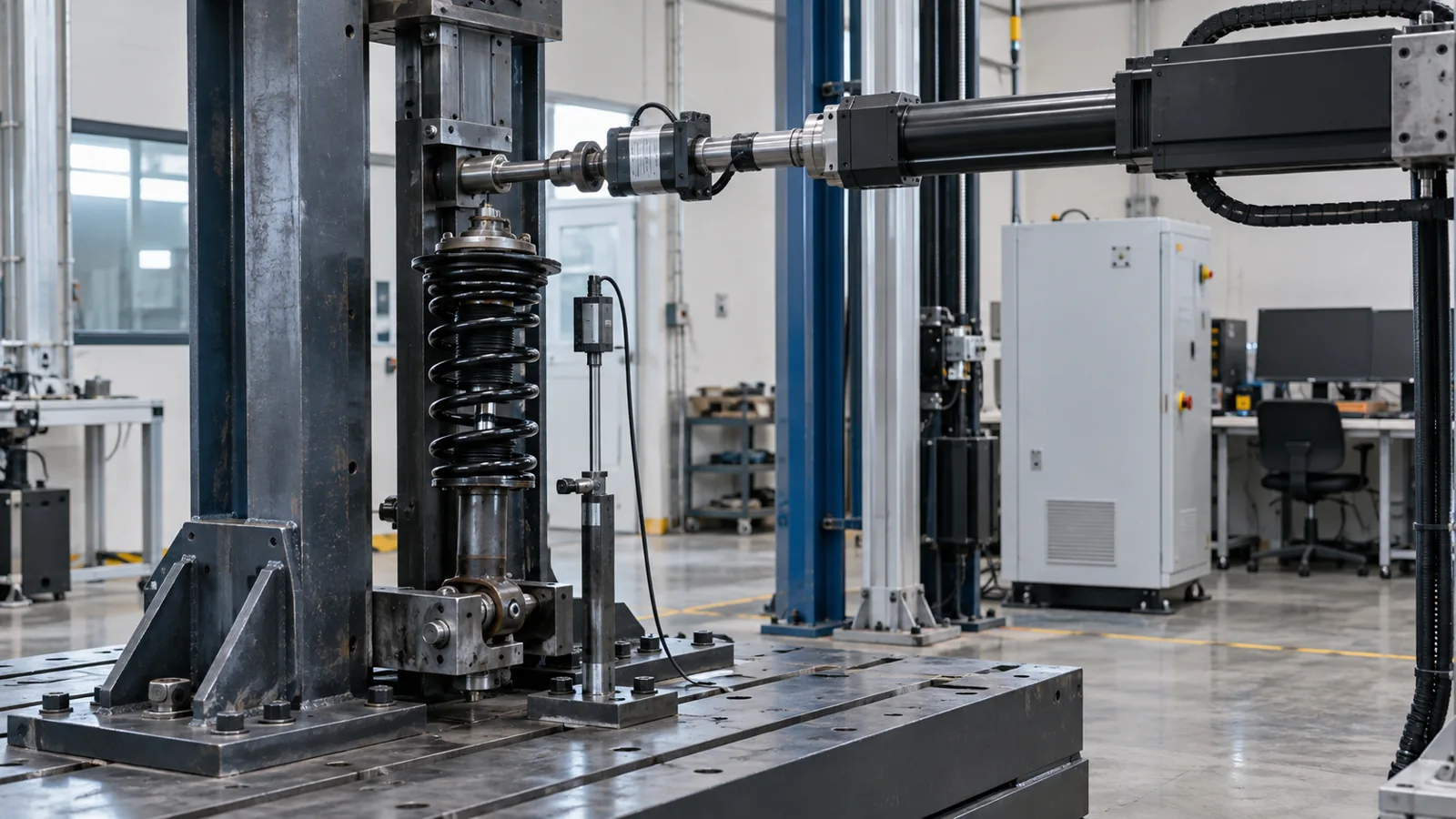
Vehicle coil-over damper; displacement-controlled durability cycling
Sinusoidal motion ±25 mm at 2 Hz
40 kg moving crosshead, fixture and participating hardware
Engineering feasibility study: assumed inputs and calculated values; conceptual equipment illustrations. Proposed checks require project approval and measured trials.
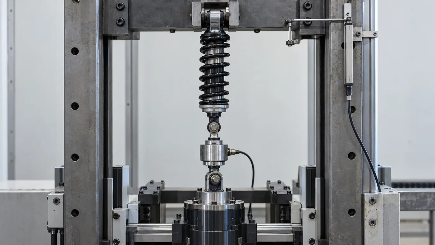
Joints, load cell and damper share the intended force axis. Review joint articulation and fixture stiffness to avoid adding unintended bending.
A separate reference measures specimen travel. Define sensor range, bandwidth, sampling, synchronization and stopping limits around the approved waveform.
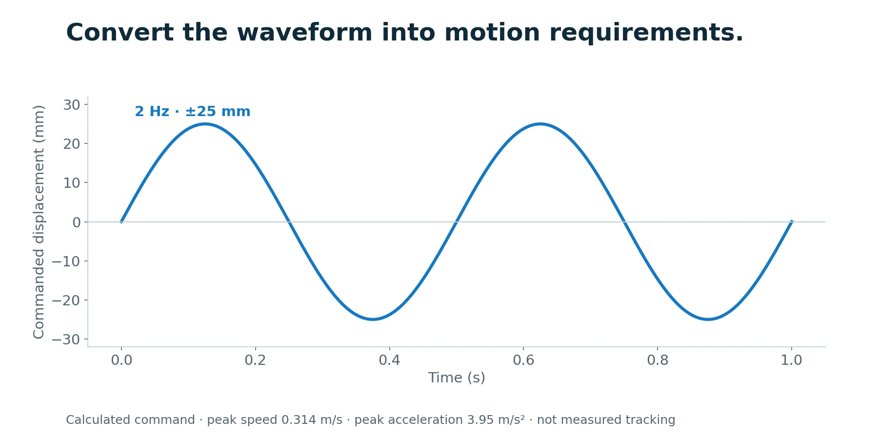
For x = 25 mm × sin(2π × 2 Hz × t), peak speed is 0.314 m/s and peak acceleration is 3.95 m/s². Doubling frequency doubles speed and quadruples acceleration. A 40 kg moving mass adds approximately 158 N inertia, separately from the specimen load.
Record specimen/fixture revision and measurement configuration; establish the neutral position and sensor zero.
Use a bounded ramp to avoid a sudden amplitude or velocity demand.
Track commanded/actual motion, force, drive demand and agreed temperature channels.
Stop on completed duration or defined force, travel, tracking or sensor condition using the approved sequence.
Store synchronized raw channels, calibration references, method revision and termination reason with the specimen ID.
Check before resetting: Tracking error increases at high frequency: Review available force-speed capability, control tuning, inertia, specimen reaction and frame dynamics. Force spikes appear at reversal: Inspect joint clearance, backlash, guide stiction, sensor mounting and waveform continuity.
Proposed tracking trial: 2 Hz and ±25 mm, measured amplitude error ≤2% after settling. This preliminary target requires controller bandwidth, sampling and sensor checks; no demonstrated tracking performance is asserted.
Record commanded and independently measured displacement, axial force and timestamp at an agreed rate providing at least 100 samples per cycle for this example. Derive amplitude, phase and peak error from the retained time series. Run a staged thermal/endurance trial before committing to the full cycle count.
Record actual value, conditions, uncertainty, result and approval. Test status: planned; measured results remain to be recorded at FAT.
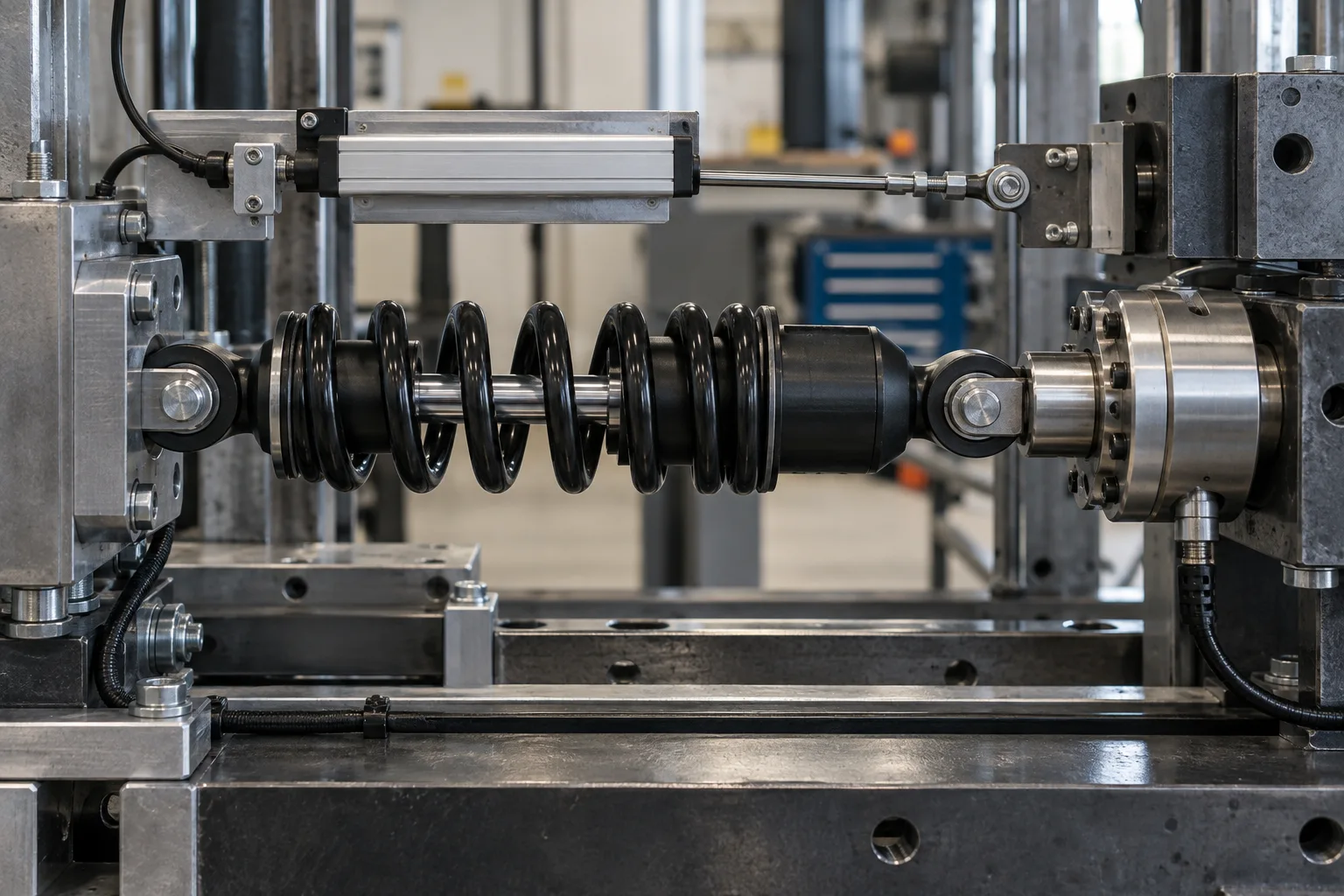
Provide the complete waveform and specimen force envelope with the RFQ. “50 mm stroke, 2 Hz” omits critical dynamic information. Agree whether the supplier provides only the motion axis or also sensor integration, controller tuning and test-data responsibility.
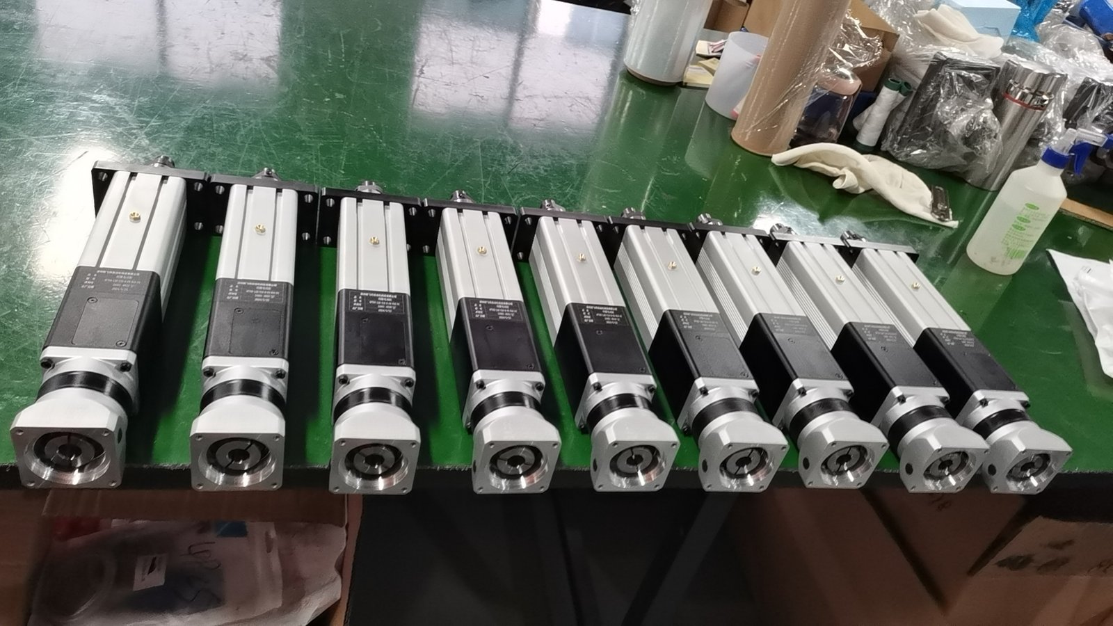
Confirm thrust versus speed, stroke, duty, mounting, motor/drive, feedback and environment together. The NFT40 photograph illustrates the product family; the study does not select that exact model.
Engineering pack: operating-cycle sizing, configuration and interface drawing, responsibility split, lubrication provisions and an agreed test plan.
No. Verify frequency content, force, velocity, acceleration, travel and duration against the actuator and fixture. Complex road-load reproduction may require a different architecture.
Choose from the waveform frequency, transient content, sensor bandwidth and analysis objective. Define anti-aliasing and channel synchronization rather than naming one universal sample rate.
Request the configuration-specific sizing review, interface drawing, supply boundary and proposed acceptance plan. This feasibility study contains assumed inputs and calculated values; it does not report a delivered customer project or completed FAT.
Share the drawing, load cycle and acceptance target. Start with a clear actuator scope and the engineering checks that matter to your machine.
Drawing · Load cycle · Control requirements
Drawing + operating cycle
Loads, interfaces + duty
Configuration + test plan
Agreed hardware + records