
Combine controlled thrust, short tooling and measured frame compliance for a maintainable press axis.
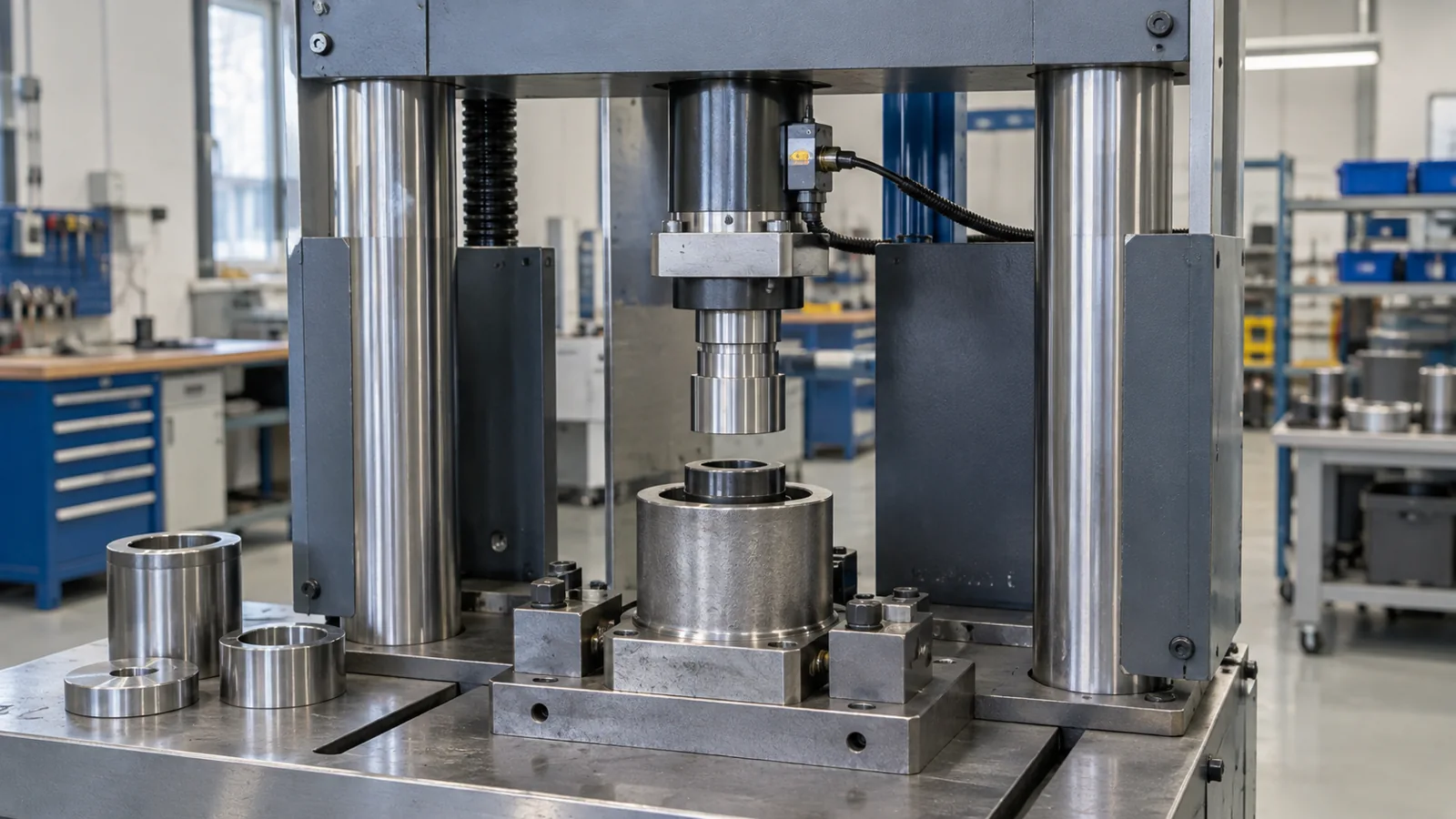
Bronze bushing pressed into a steel housing
100 kN working force; 120 mm illustrative usable actuator travel
2 mm/s insertion; bounded 1 s final dwell
Engineering feasibility study: assumed inputs and calculated values; conceptual equipment illustrations. Proposed checks require project approval and measured trials.
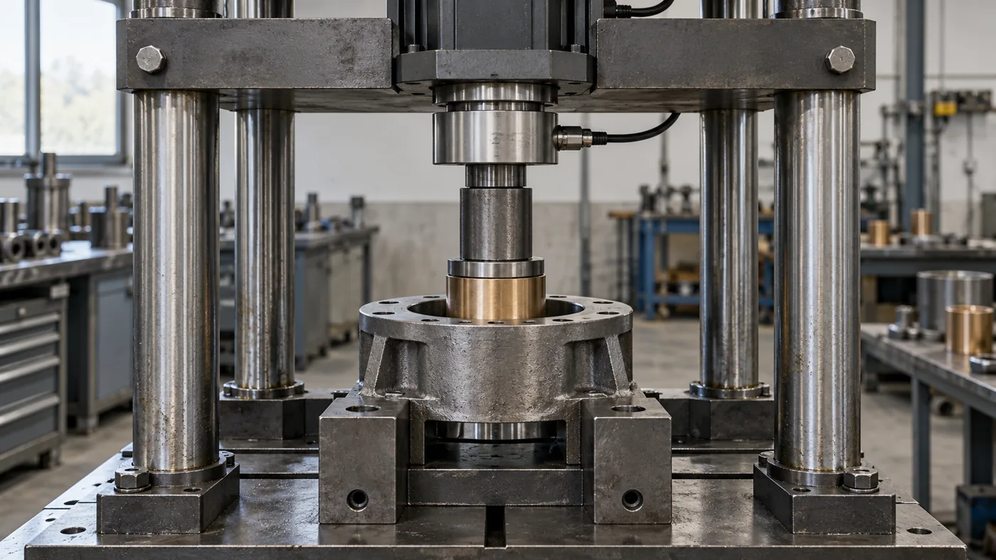
The cylinder flange, frame, guided platen, mandrel and housing support form the reaction loop. Check plates, bolts and local contacts at full working load.
Practical shielding and accessible lubrication protect the screw. Covers must remain clear of moving interfaces and permit cleaning and inspection.
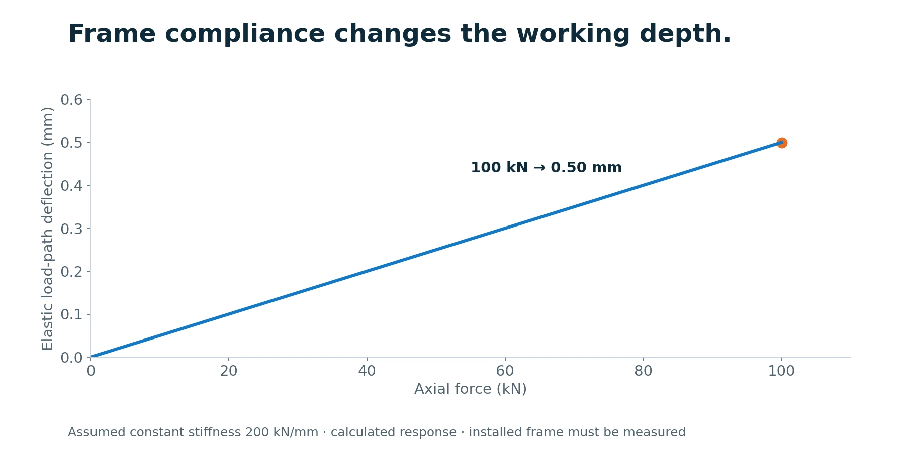
At 100 kN and assumed 200 kN/mm axial stiffness, elastic deflection is 0.50 mm. With 5 mm screw lead and 90% efficiency, torque is 88.4 N·m. The 200 W process power at 2 mm/s does not establish motor size; peak current, dwell and full-cycle heating remain.
Check the housing support, bushing orientation, mandrel condition, recipe and sensor readiness.
Move to a qualified clearance and search for contact without using the workpiece as an uncontrolled hard stop.
Press at the validated speed while monitoring force and depth; abort on a defined abnormal trace.
Apply the approved bounded dwell, then unload in a controlled way before interpreting the final measurement.
Identify pass/reject from the qualified method and retain the process trace and tooling revision.
Check before resetting: Force rises with no expected insertion: Check interference, burrs, lubrication and alignment. Do not solve every obstruction by raising actuator torque. Final depth varies with force: Investigate frame/tool compliance, sensor datum and elastic recovery of the assembled parts.
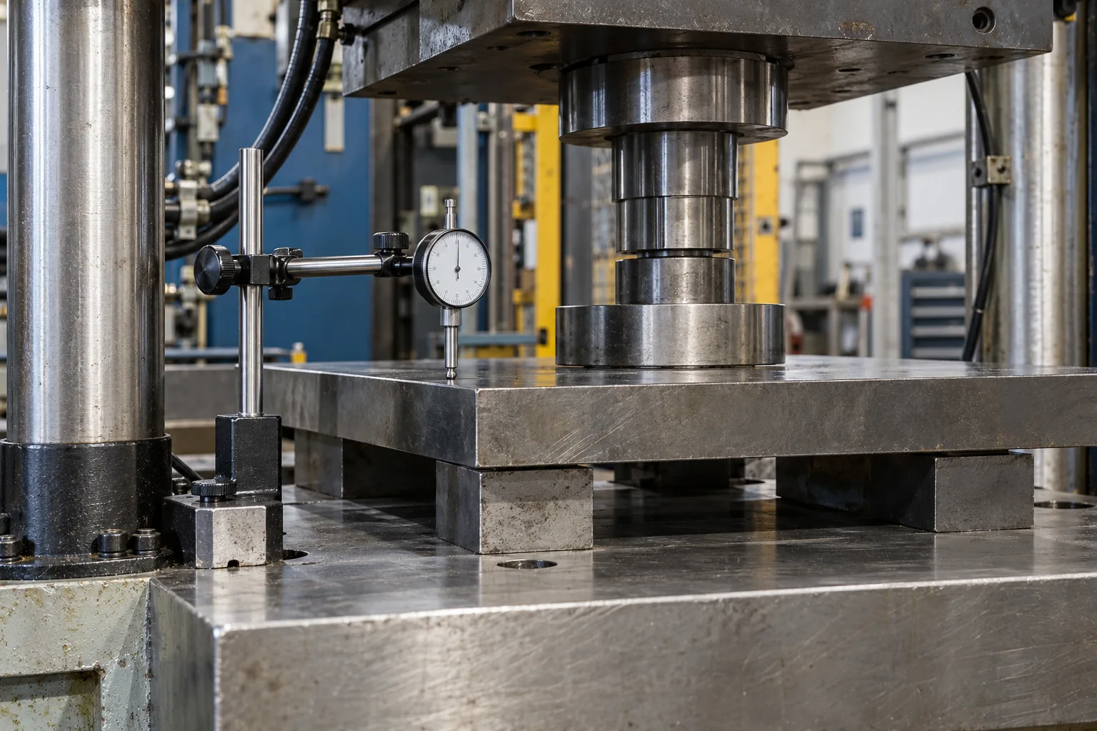
Proposed structure trial: measure ≤0.50 mm elastic frame deflection at the 100 kN example load, and verify residual set against the structural design allowance after unloading. This is a preliminary frame target, not proof of structural safety or actuator capability.
Use a calibrated axial load cell and independent frame/platen references at incremental loads approved by the structure designer. Confirm tooling concentricity and supported contact. Run the agreed loaded duty cycle and inspect screw temperatures, shielding and lubrication access. Process acceptance requires qualified bushing parts.
Record actual value, conditions, uncertainty, result and approval. Test status: planned; measured results remain to be recorded at FAT.
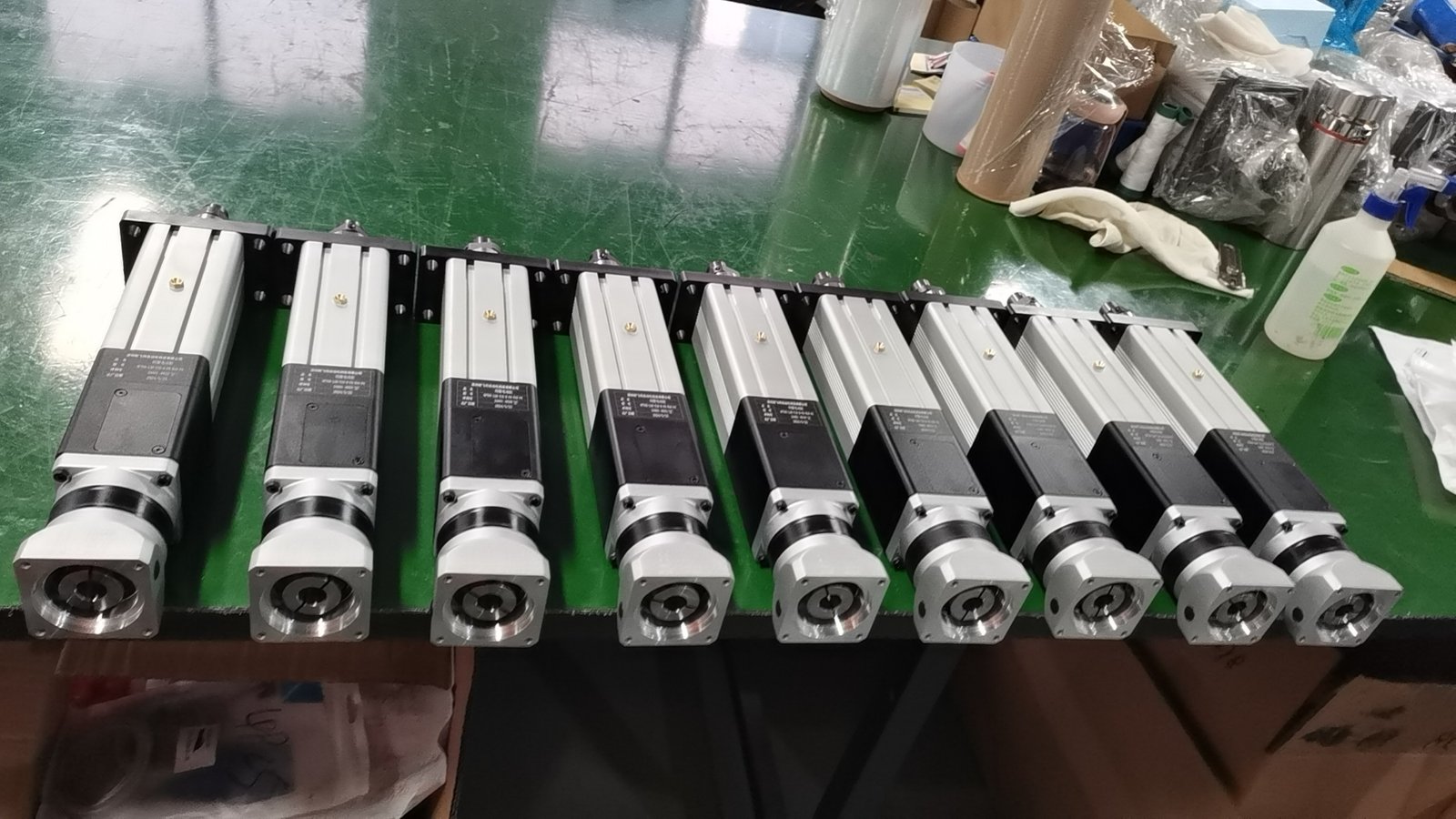
Ask for the reviewed working point and continuous-duty assumptions, not merely a maximum thrust number. The supply boundary should identify the cylinder, motor/transmission, frame, sensor and control responsibilities, plus the service provisions that keep a high-force axis maintainable.
Confirm thrust versus speed, stroke, duty, mounting, motor/drive, feedback and environment together. The NFT40 photograph illustrates the product family; the study does not select that exact model.
Engineering pack: operating-cycle sizing, configuration and interface drawing, responsibility split, lubrication provisions and an agreed test plan.
No. Motor torque, current, peak duration, dwell and thermal duty still matter. Process power at one phase does not determine the complete motor/drive selection.
This study concerns controlled quasi-static bushing assembly. Impact loading requires a separate engineering assessment and may demand a different technology.
Request the configuration-specific sizing review, interface drawing, supply boundary and proposed acceptance plan. This feasibility study contains assumed inputs and calculated values; it does not report a delivered customer project or completed FAT.
Share the drawing, load cycle and acceptance target. Start with a clear actuator scope and the engineering checks that matter to your machine.
Drawing · Load cycle · Control requirements
Drawing + operating cycle
Loads, interfaces + duty
Configuration + test plan
Agreed hardware + records