
Keep tool changes repeatable with a stable datum, locked recipes and a cycle-based actuator review.
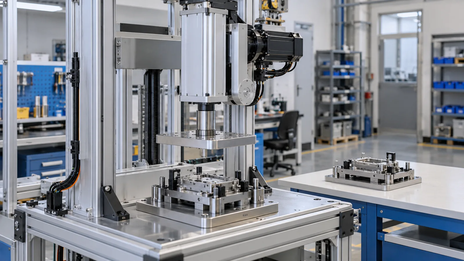
Variant pin or bushing assembly in a guided press cell
12 kN working thrust; 150 mm travel; illustrative 8 s machine cycle
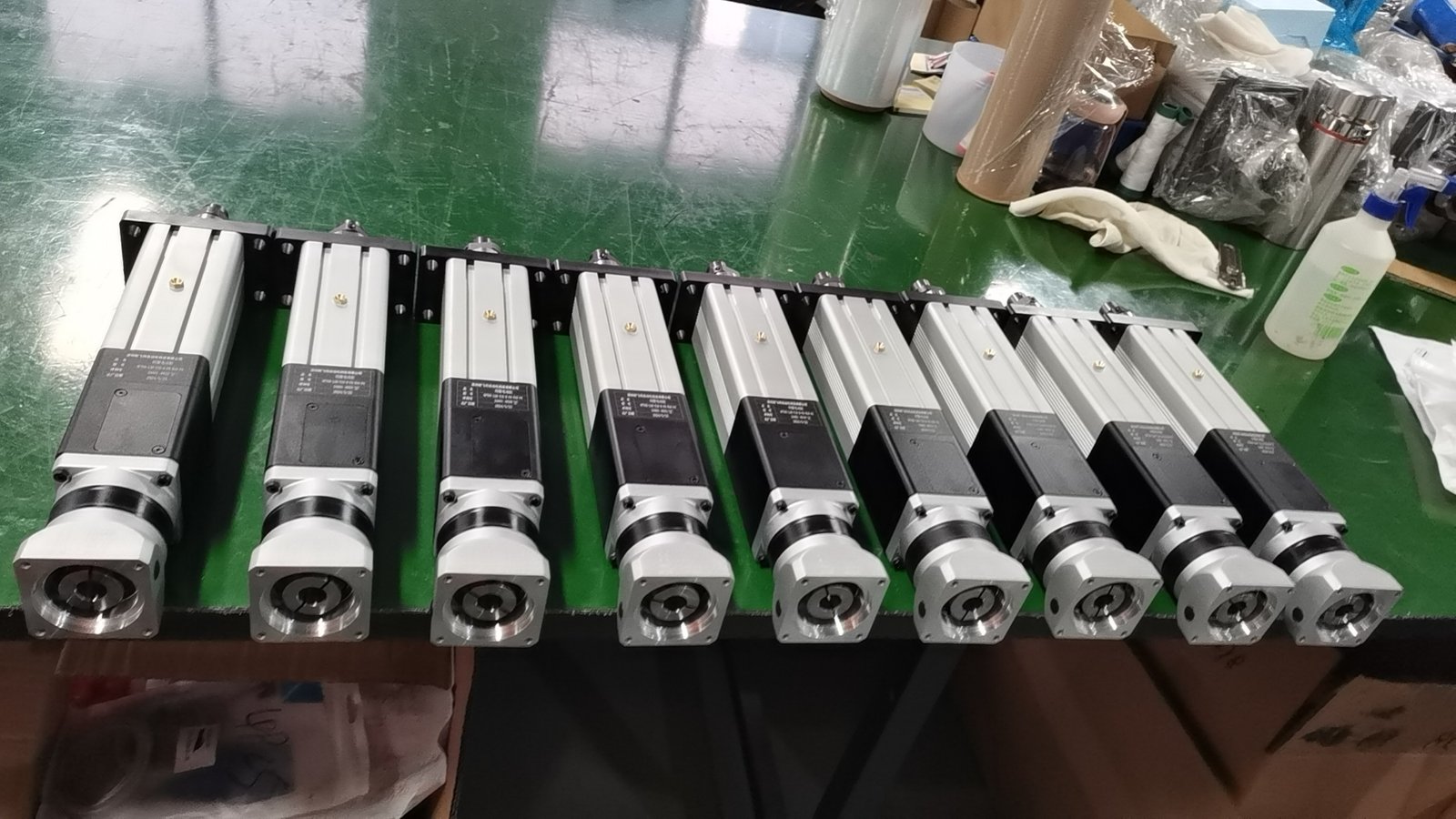
Folded-back arrangement where axial space is constrained
Engineering feasibility study: assumed inputs and calculated values; conceptual equipment illustrations. Proposed checks require project approval and measured trials.
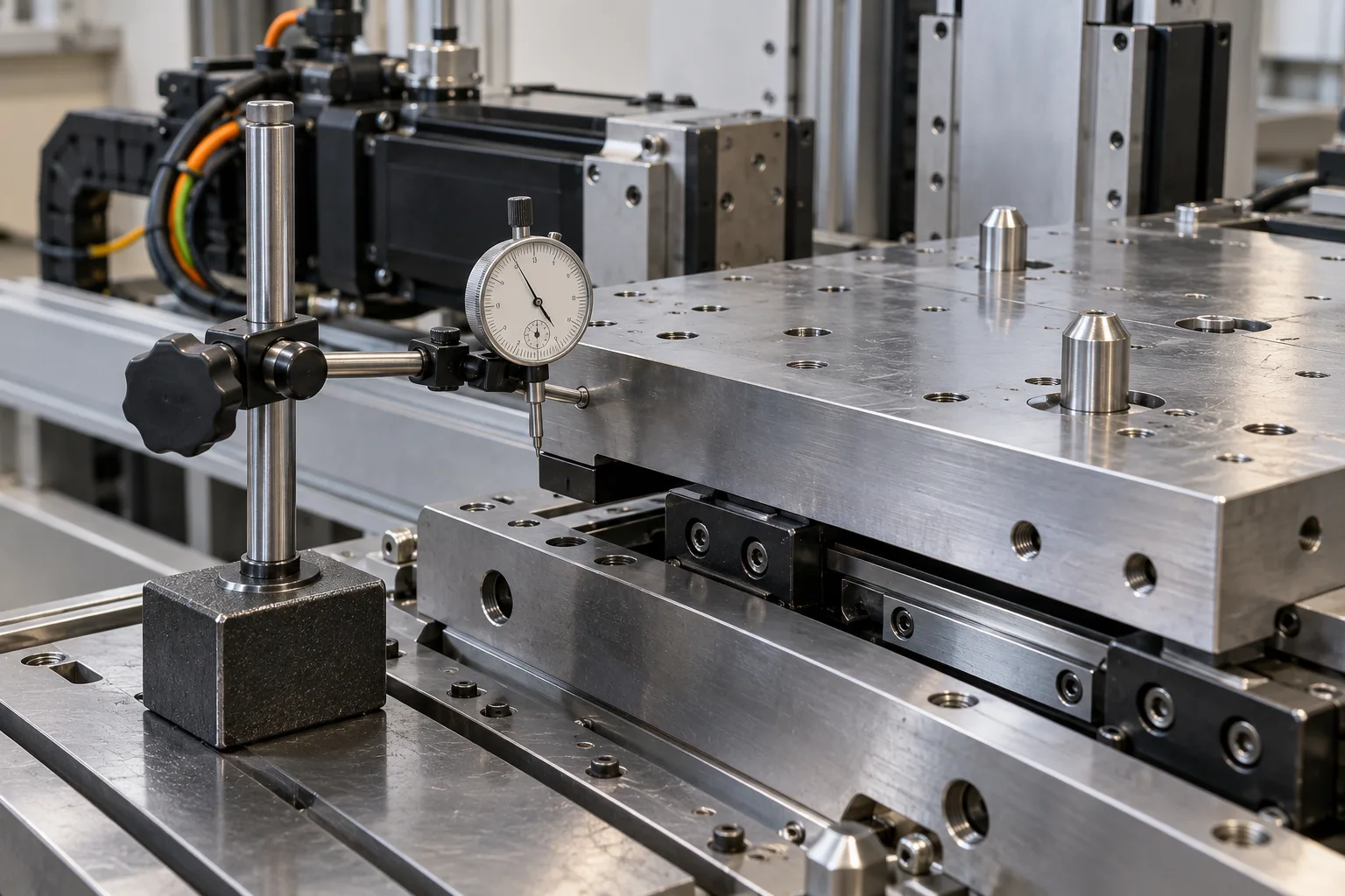
Locating pins, clean datums and a verified tool lock define the working height. Link the tool identity to the approved recipe before enabling full-speed motion.
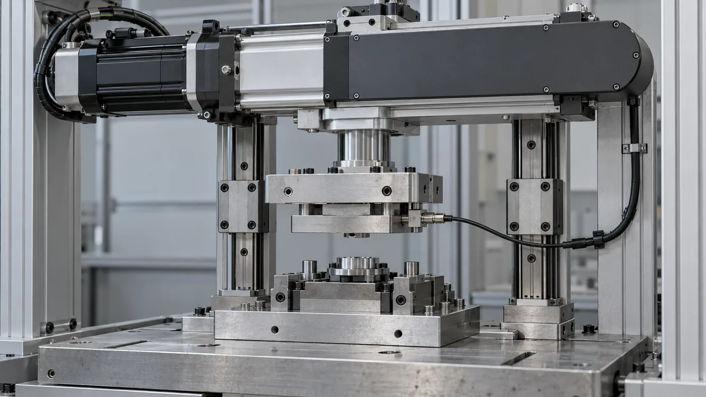
The platen guides carry moments. Compare folded-back and inline drive against available space, transmission stiffness, lubrication and motor-removal clearance.
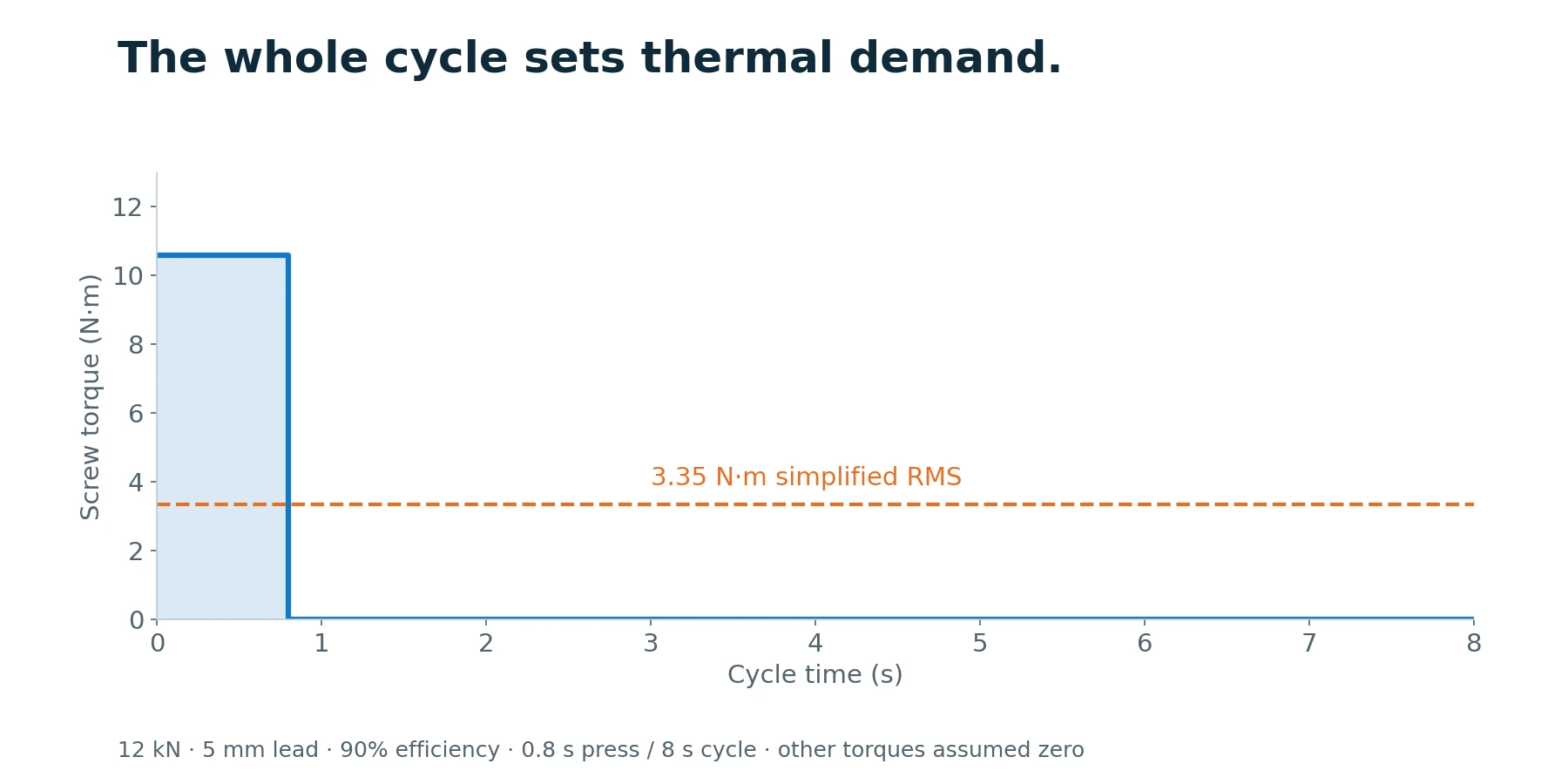
The 12 kN / 5 mm lead example needs 10.6 N·m at 90% assumed efficiency. A 0.8 s press in an 8 s cycle contributes 3.35 N·m RMS only if every other torque is zero. Actual sizing includes acceleration, holding, friction and transmission losses.
Confirm tool lock, product recipe, part presence and machine-ready conditions.
Use the validated tool-specific clearance, speed and travel limits.
Search within the permitted contact region; an unexpected datum ends the attempt.
Execute the qualified pressing profile and collect force/depth evidence.
Evaluate the cycle, retract, release the assembly and retain recipe/tooling revision with the result.
Check before resetting: Different depth after a tool change: Inspect plate seating, datum cleanliness, locking and tool length before changing the recipe offset. Motor temperature rises over a shift: Review RMS demand, dwell, cooling, friction, alignment and transmission condition across the actual cycle.
Proposed changeover check: 10 consecutive cycles per approved tooling set, with unloaded tool-depth repeatability within ±0.10 mm. Final tolerance follows the component drawing and measurement budget.
Measure frame/platen deflection at 25%, 50%, 75% and 100% of the 12 kN example load. Run each recipe at the intended eight-second cycle until temperature stabilizes under an agreed definition, then log temperatures and tracking errors. Validate tool-ID/recipe mismatch and recovery.
Record actual value, conditions, uncertainty, result and approval. Test status: planned; measured results remain to be recorded at FAT.
A credible quotation identifies what is included: cylinder and motor interface, or a broader motion package. The press frame, tooling, sensor calibration, PLC software and guarding must each have an owner. This prevents the actuator price from being mistaken for the installed cost of a qualified assembly cell.
Confirm thrust versus speed, stroke, duty, mounting, motor/drive, feedback and environment together. The NFT40 photograph illustrates the product family; the study does not select that exact model.
Engineering pack: operating-cycle sizing, configuration and interface drawing, responsibility split, lubrication provisions and an agreed test plan.
Compare the measured working force, duty, holding and envelope first. A hydraulic rating often exceeds the real process force, but high-force dwell and impact may make an electric conversion unsuitable.
A standard holding brake has a specific component function. The machine builder must determine the stopping, load support and safety functions of the complete press.
Request the configuration-specific sizing review, interface drawing, supply boundary and proposed acceptance plan. This feasibility study contains assumed inputs and calculated values; it does not report a delivered customer project or completed FAT.
Share the drawing, load cycle and acceptance target. Start with a clear actuator scope and the engineering checks that matter to your machine.
Drawing · Load cycle · Control requirements
Drawing + operating cycle
Loads, interfaces + duty
Configuration + test plan
Agreed hardware + records