
Apply the approved load schedule while measuring specimen movement independently of the actuator encoder.
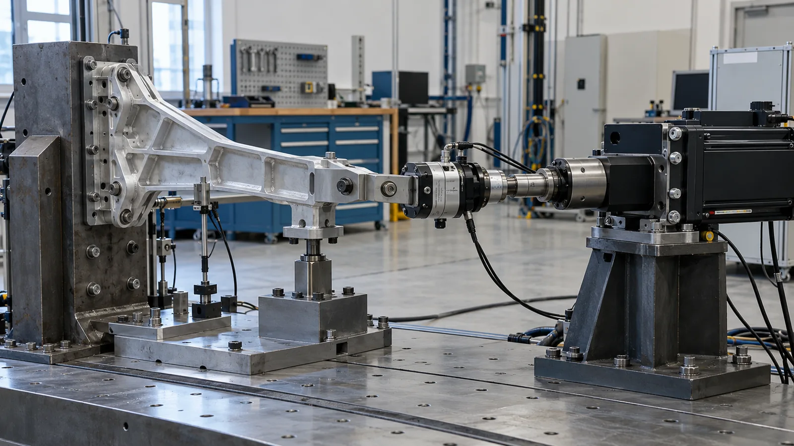
Aluminum bracket in an axial ground-load fixture
5 kN load point; 100 mm illustrative usable actuator travel
Bounded ramp, hold and unload under the approved test method
Engineering feasibility study: assumed inputs and calculated values; conceptual equipment illustrations. Proposed checks require project approval and measured trials.
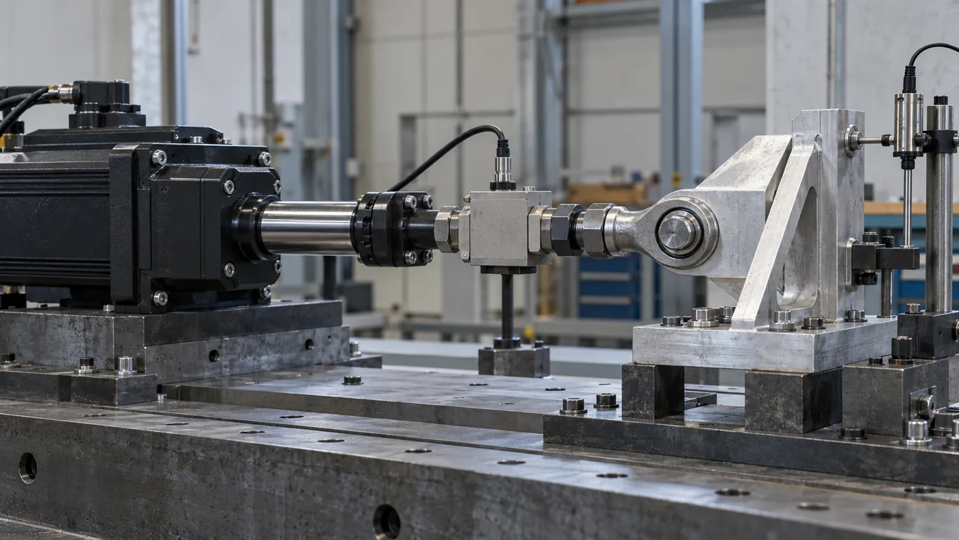
Define clamping, joint freedoms, preload and load direction. A rated articulated connection can reduce bending only within its approved geometry and clearance.
Place the force sensor in the specimen load path and displacement endpoints at the method’s datums. Preserve calibration and configuration identity with raw channels.
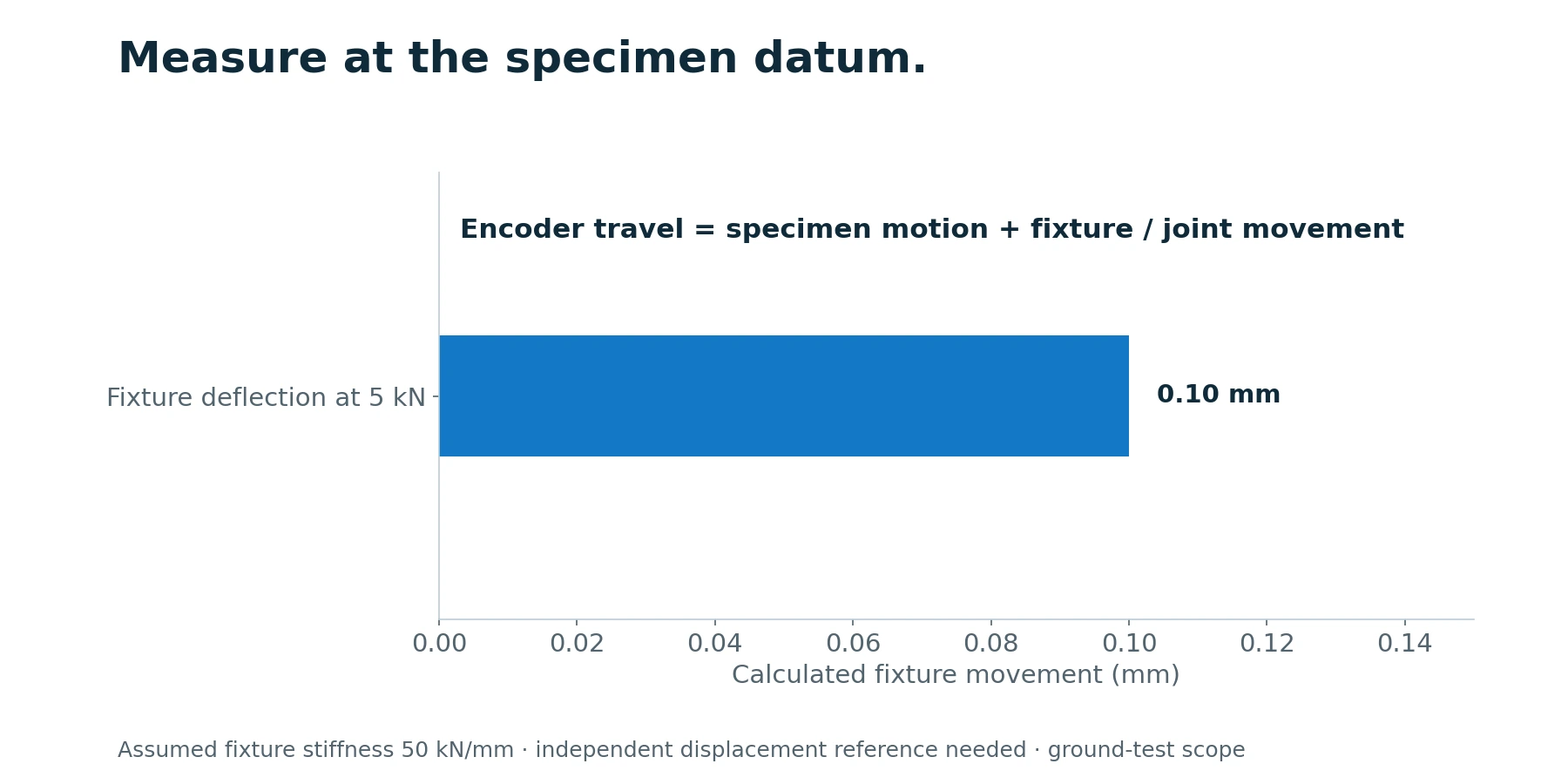
An assumed 50 kN/mm fixture stiffness produces 0.10 mm movement at 5 kN. Encoder travel includes fixture and joint movement, so it cannot alone establish specimen deformation. At 10 mm lead and 90% efficiency, screw torque is 8.84 N·m; 20 mm/s needs 120 rpm.
Record specimen, fixture, actuator/drive and method revisions plus calibration references.
Establish the defined neutral state and approved preload while recording the measurement channels.
Apply the approved schedule; monitor tracking and independent force/displacement limits.
Unload using the specified profile and preserve any residual displacement or relevant recovery measurements.
Retain raw channels, timestamps, test settings, configuration identity and termination reason before reporting the result.
Check before resetting: Force is stable but displacement drifts: Review specimen behavior, fixture compliance, sensor drift, temperature and the measurement reference separately. Measured bending appears in an axial test: Check alignment, joint articulation, fixture restraint and eccentric sensor/tool mounting.
Proposed load-hold trial: measured force within ±1% of the 5 kN example setpoint for a 60 s dwell after settling. This preliminary target requires an agreed uncertainty budget and test-owner approval; no flight or program qualification is claimed.
Calibrate the load channel and specimen displacement reference. Run approved incremental load points and the 60 s dwell, recording drift and settling. Compare actuator travel against independent specimen displacement to quantify fixture compliance. Verify limits and termination conditions under an approved test procedure.
Record actual value, conditions, uncertainty, result and approval. Test status: planned; measured results remain to be recorded at FAT.
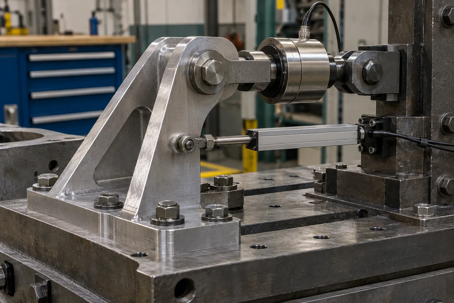
A useful supplier review starts with the approved method, specimen reaction envelope and uncertainty objective. Agree actuator/drive supply, fixture engineering, sensor calibration, controller implementation and report ownership. This scope is more meaningful than a generic “aerospace-grade electric cylinder” label.
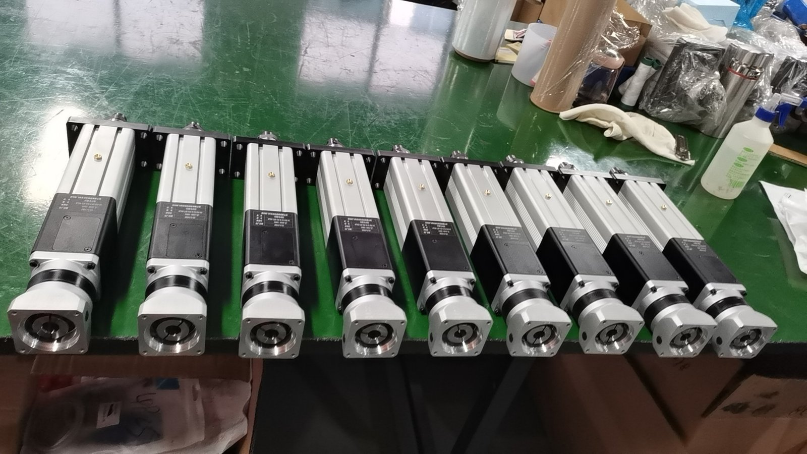
Confirm thrust versus speed, stroke, duty, mounting, motor/drive, feedback and environment together. The NFT40 photograph illustrates the product family; the study does not select that exact model.
Engineering pack: operating-cycle sizing, configuration and interface drawing, responsibility split, lubrication provisions and an agreed test plan.
No. The page describes a ground-test motion axis. Airborne use needs a separately designed and qualified configuration.
A traceable configuration, approved method revision, calibration chain, specimen identity, reference/zero procedure and synchronized raw data are all needed.
Request the configuration-specific sizing review, interface drawing, supply boundary and proposed acceptance plan. This feasibility study contains assumed inputs and calculated values; it does not report a delivered customer project or completed FAT.
Share the drawing, load cycle and acceptance target. Start with a clear actuator scope and the engineering checks that matter to your machine.
Drawing · Load cycle · Control requirements
Drawing + operating cycle
Loads, interfaces + duty
Configuration + test plan
Agreed hardware + records