
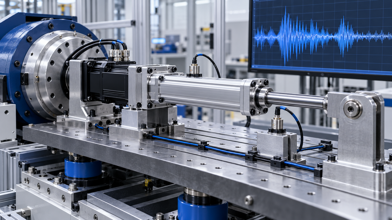
In brief: Servo electric cylinder vibration can result from load mismatch, motion tuning, alignment, feedback noise or a flexible machine frame. Record when the vibration starts before changing settings.
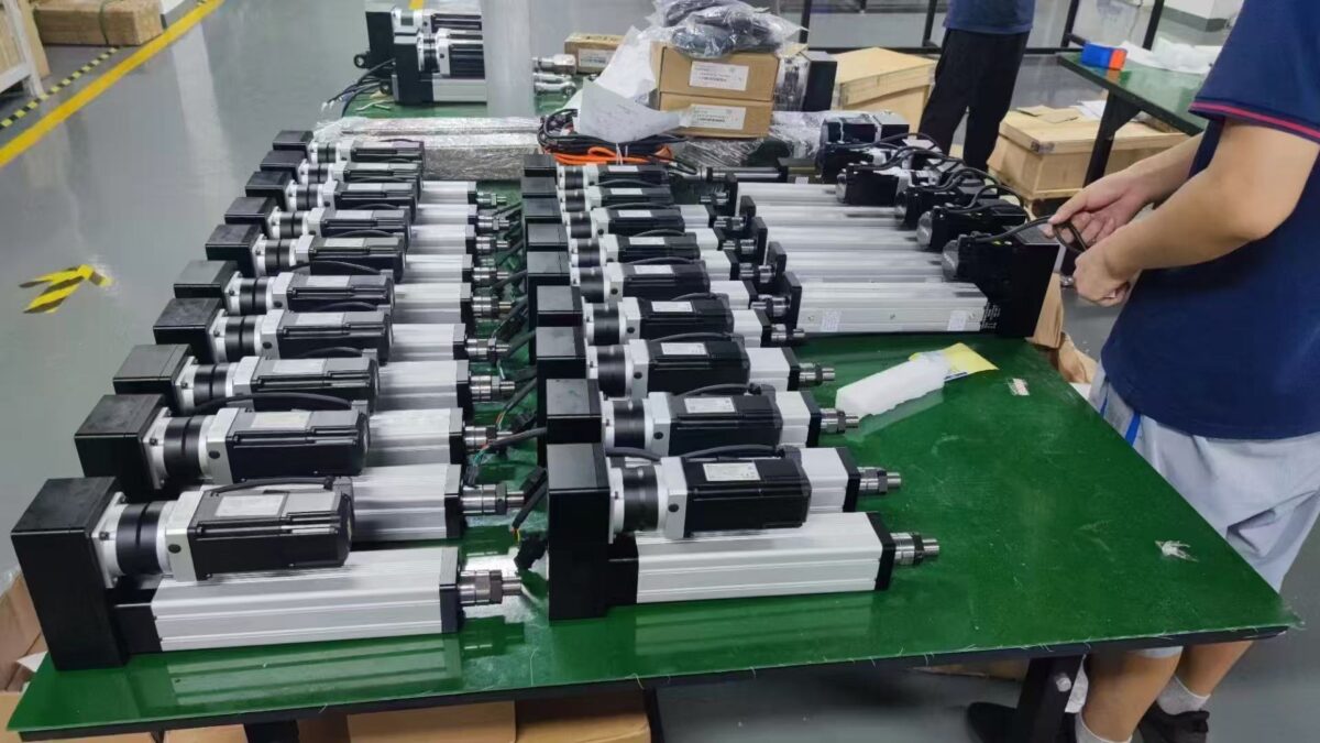
Five servo electric cylinder vibration causes
Vibration at a fixed speed suggests a different problem from vibration only at reversal or near a load limit. Capture the commanded position, actual position, motor current, speed and alarm history. Compare unloaded and loaded cycles where the machine can be operated safely. This evidence helps separate a mechanical fault from a control response.
1. Load inertia and side force
An undersized axis or an unsupported off-axis load can make the carriage and rod oscillate. Confirm moving mass, acceleration and orientation against the chosen actuator and motor. Use external guidance for lateral forces; the cylinder rod is not a substitute for a guide rail. If the symptom follows a particular workpiece, check clamping and load variation first.
2. Acceleration and servo tuning
A sharp acceleration command or excessive control gain can excite a compliant fixture. Compare a slower motion profile with the production profile and follow the drive manufacturer’s tuning procedure. Change one parameter at a time, record the result and restore the baseline if performance worsens. Do not mask binding by lowering gain.
3. Misalignment and loose mounting
Inspect the mounting face, couplings, bolts and external guide alignment. A joint that binds at one point in the stroke can produce cyclic current peaks and vibration. Disconnect and inspect only under the machine’s approved isolation procedure. Correct the mechanical source before retuning the drive.
4. Encoder or electrical interference
Intermittent feedback faults may appear as position jitter or drive alarms. Check connector seating, cable damage, shielding and grounding against the drive and machine wiring manuals. Route encoder and power cables as specified by the system designer. Compare recorded feedback with physical motion rather than assuming every trace fluctuation is mechanical.
5. Flexible support structure
A thin bracket, loose rail or resonant frame can amplify an otherwise small excitation. Inspect structural joints and repeat the test at a lower speed. If a narrow speed band triggers the symptom, involve the machine designer in a stiffness and resonance review.
Diagnosis checklist and next steps
- Record speed, stroke position, load, current, position error and alarms at the onset of vibration.
- Inspect alignment, guide rails and fasteners before changing drive settings.
- Test a controlled lower acceleration and compare the trace.
- Check feedback wiring and the drive manual if vibration coincides with an encoder alarm.
- Document the corrective action and retest the complete duty cycle.
See our failure causes guide and load deviation diagnostic guide for related symptoms. For a model-specific diagnosis, send NEFEIT engineering the actuator model, mounting drawing, load and trend data. The THK technical resources provide further background on linear guides and mechanical alignment; follow the actual component and drive documentation for limits.