Servo electric cylinder duty cycle is the percentage of a repeating cycle during which the actuator is actively moving or producing the defined working action. Calculate it as active time divided by total cycle time, then multiply by 100. That percentage is useful, but it is not enough to select an actuator: the engineer also needs force, speed, acceleration and dwell for every segment of the cycle.
The basic duty-cycle calculation
For a repeating cycle:
Duty cycle (%) = active time / total cycle time × 100
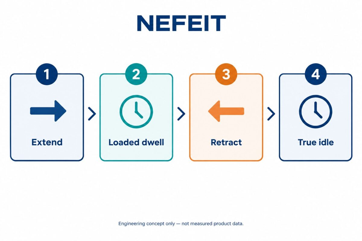
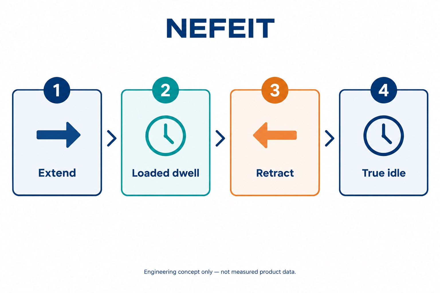
Suppose an axis extends for 2.0 seconds, holds process force for 1.0 second, retracts for 2.0 seconds and then remains idle for 5.0 seconds. If “active time” for the initial screening includes extend, force-hold and retract, the active time is 5.0 seconds and the total cycle is 10.0 seconds:
5.0 / 10.0 × 100 = 50%
The definition of active time must be agreed for the selected motor, drive and actuator. A stationary force-hold can still create motor current and heat even when linear speed is zero. Do not automatically treat every dwell as thermal rest.
Why one percentage does not size the cylinder
Two machines can both have a 50% duty cycle and impose very different loads.
| Cycle A | Cycle B |
|---|---|
| Moderate force at nearly constant speed | High acceleration, brief process peak and rapid reversal |
| Long, lightly loaded moves | Short, heavily loaded moves |
| Low holding force during dwell | Significant force maintained at zero speed |
The same on/off ratio does not describe peak thrust, motor torque, screw speed, acceleration demand or how heat is distributed through the cycle. That is why a complete selection begins with a motion profile rather than a single “maximum thrust” number.
The NEFEIT servo electric cylinder selection guide provides the broader input list. The workflow below focuses on the timing and load data behind the duty-cycle check.
Build the motion profile segment by segment
Create one row for every distinct phase. Do not combine phases that have different speed, force or direction.
1. Define position and direction
Record the start and end position for each move. State whether the axis is horizontal, vertical or inclined. For vertical axes, gravity changes the required force between upward and downward motion and also affects power-loss behavior.
2. Record moving mass and external force
Separate the mass being accelerated from the process force at the tooling. Include friction or other known resistance where it can be supported. If the value is estimated, label it as an estimate instead of presenting it as measured data.
3. Add speed, acceleration and deceleration
Average speed alone can hide a demanding acceleration peak. Provide the target velocity and the time or distance allowed to accelerate and decelerate. If the controller uses an S-curve or another motion law, include that information.
4. Identify process and holding phases
A press, clamp or test axis may reach zero speed while it continues to apply force. Record the force and duration of that phase. It may contribute to thermal demand even though the rod is stationary.
5. Include every dwell
Add pauses between moves and the idle time between finished parts. Bosch Rexroth notes that dwell times belong in duty-cycle and thermal determination. The distribution of those pauses can matter; ten short pauses are not automatically equivalent to one long cooling interval.
6. Add production exposure
State cycles per minute or hour, shifts per day, hours per shift and expected operating days. A short demonstration cycle does not represent a machine that repeats the same profile throughout production.
A practical worksheet for engineering review
Use a table like this when requesting a configuration review:
| Segment | Direction | Distance | Time | Speed | Acceleration | Axial force | Hold at zero speed? |
|---|---|---|---|---|---|---|---|
| Extend | + | ___ mm | ___ s | ___ mm/s | ___ mm/s² | ___ N | No |
| Process | — | 0 mm | ___ s | 0 | 0 | ___ N | Yes/No |
| Retract | − | ___ mm | ___ s | ___ mm/s | ___ mm/s² | ___ N | No |
| Idle | — | 0 mm | ___ s | 0 | 0 | 0/___ N | Yes/No |
Also send mounting orientation, available installation envelope, accuracy and repeatability requirements, ambient temperature, contamination, lubrication constraints, proposed motor and drive, supply voltage and the expected service-life target.
Peak demand, RMS demand and life are different checks
Peak force is the highest short-duration demand during acceleration, deceleration or process contact. Continuous or RMS demand represents the sustained heating effect of the varying cycle. Mechanical life adds other considerations, including screw load history, travel and operating conditions.
These checks interact but are not interchangeable. An actuator may satisfy a brief peak without satisfying the continuous thermal requirement. Conversely, a low average load does not excuse a peak outside the permitted operating envelope. Final validation must use the configuration-specific speed-force curves, motor data, drive limits and life calculation.
Common duty-cycle mistakes
- Using only extend time: Retraction, loaded dwell and other powered phases may also matter.
- Calling every stop “off time”: A stationary axis can continue to produce force and heat.
- Combining maximum force and maximum speed: Catalogue maxima may describe different operating points.
- Ignoring acceleration: Short moves can be dominated by acceleration and deceleration.
- Omitting orientation: Gravity affects vertical-axis force and holding requirements.
- Reporting cycles per minute without segment timing: Frequency alone does not reveal the force-speed-time profile.
- Treating a calculated percentage as approval: Allowable duty depends on the actual actuator, screw, motor, drive, environment and cycle.
Frequently asked questions
Is 100% duty cycle always possible with a servo electric cylinder?
Not universally. Continuous operation depends on the selected actuator architecture, screw, motor, drive, load, speed, thermal environment and manufacturer limits. Validate the exact configuration at the required operating point.
Does holding force at zero speed count as duty?
It can contribute to motor current and heating. Record the force and duration, then let the motor-drive and actuator review determine how it is treated.
What if the motion profile is not final?
Provide a conservative range and clearly mark assumptions. It is better to compare defined scenarios than to hide uncertainty inside one peak-force value.
What should I send NEFEIT?
Send the segment table, load and process-force information, stroke, velocity, acceleration, orientation, dwell, production schedule, environment, mounting drawing and motor/control requirements. NEFEIT can then review an appropriate servo electric cylinder configuration against the complete cycle.
Turn the cycle into a reviewable specification
A useful duty-cycle number comes from a useful motion profile. Before selecting a cylinder, document what the axis does, how hard it works, how fast it moves and how long each phase lasts. Then validate peak, continuous, thermal and life requirements together.
For a configuration review, send NEFEIT your force-speed-time table and machine drawing through the engineering resources page.
Engineering references
- Bosch Rexroth: Electro-mechanical cylinder selection steps
- Kollmorgen: Electric cylinder selection guide
- Schaeffler: Actuator selection assistant