
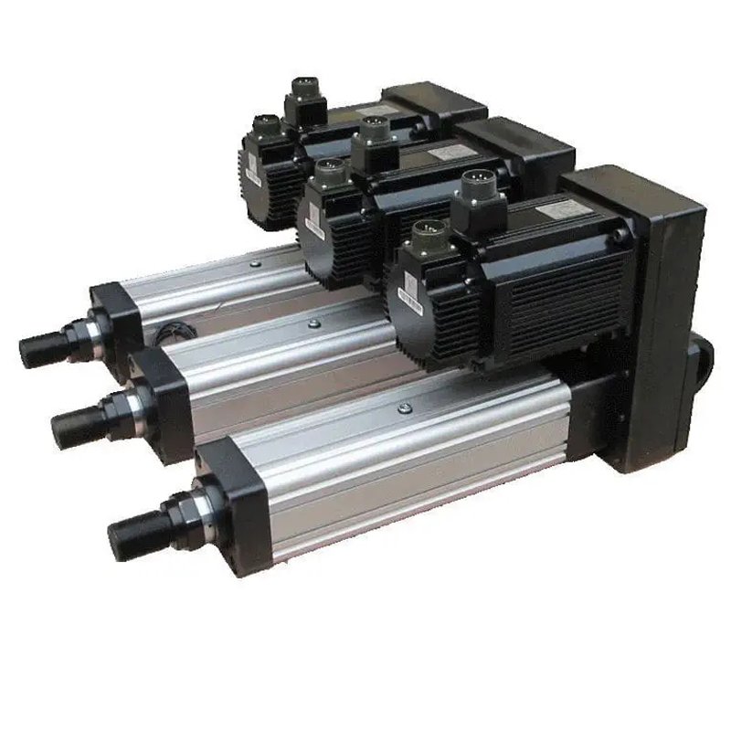
In brief: How servo electric cylinders work: a servo motor rotates a screw or other transmission, moving a guided nut and rod. Encoder feedback helps the drive track commanded motion.
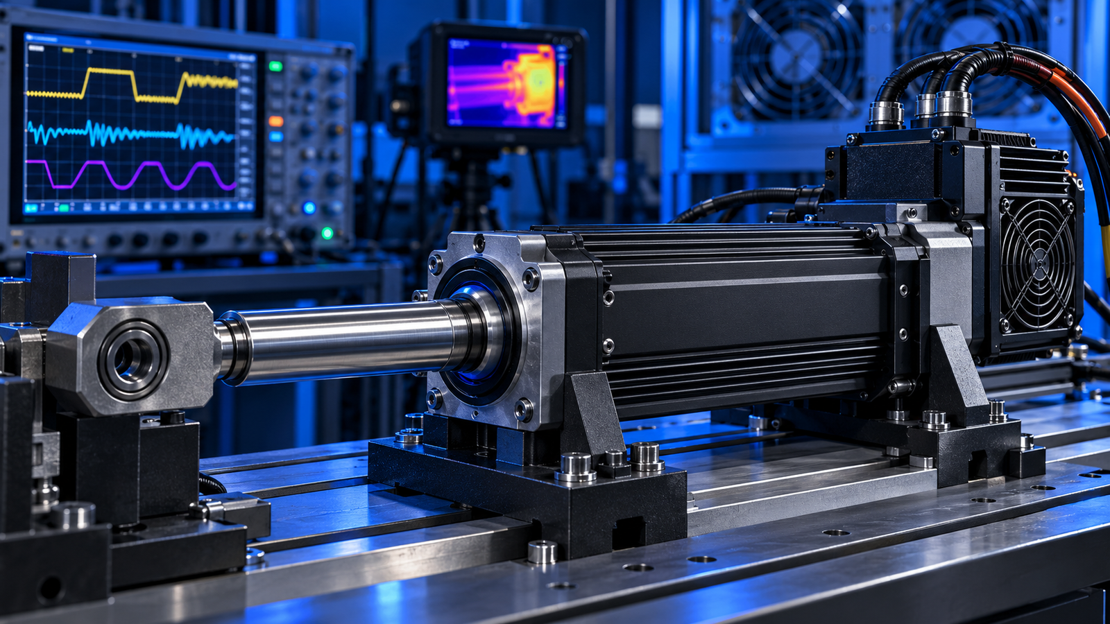
How servo electric cylinders work: components
The servo motor turns a coupling or belt that rotates a ball screw or roller screw. The nut travels along the screw and moves the rod or carriage. Bearings support the screw, while guides and anti-rotation features keep the output moving along the intended axis. A matching servo drive supplies current and processes encoder feedback.
How closed-loop control works
The controller commands a position or velocity profile. The drive compares that command with encoder feedback and adjusts motor current. The mechanical transmission converts motor torque into axial thrust. Force may be estimated from current, but a calibrated load cell is needed when the process requires direct force measurement. Friction, screw efficiency and acceleration all affect the relationship between current and output force.
What determines performance?
- Thrust and speed: screw lead, motor torque, drive capacity and duty cycle must be evaluated together.
- Repeatability: feedback, backlash, stiffness, guides and load conditions matter.
- Service life: bearing and screw loading, side force, lubrication and operating temperature affect wear.
Typical use cases
Servo electric cylinders can be used for programmable pressing, lifting, positioning and assembly where the application benefits from controlled motion profiles and feedback. Suitability depends on the complete machine design, not the actuator alone.
Start with our selection guide, compare the servo electric cylinder range, or send operating requirements to NEFEIT engineering.
Application check
Motor rotation passes through a coupling or belt into the screw. The nut converts that rotation into linear travel, while bearings and guides manage the load path. Screw lead links motor revolutions to travel, but backlash, friction and structural deflection affect tool position. Verify the installed axis with a separate measurement when accuracy is critical.