

In brief: Flight simulation motion platform actuators must be selected as a coordinated system. A single cylinder rating cannot predict the motion, workspace or safety of the complete platform.
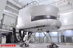
flight simulation motion platform actuators: engineering checks
Use the application drawing, motion profile and exact component manuals. Record the operating baseline before changing settings so that a correction can be verified under the same load and cycle.
Define the motion envelope
Specify payload, center of gravity, platform geometry and required pitch, roll, heave and other degrees of freedom. Compute actuator stroke and speed over the entire workspace, including worst-case combinations. Avoid assuming an axis can provide its peak force everywhere.
Synchronize axes
Motion cues require coordinated trajectories and measured feedback. Account for controller update rate, communication delay, backlash and structural stiffness. Validate the platform response with a representative payload and independent measurements.
Review mechanical loads
Calculate axial force and joint angles at extreme poses. Use bearings and guides that carry transverse loads and moments. A rigid mounting scheme that binds under motion can damage a screw or distort the platform.
Plan safety and commissioning
Define emergency stop, travel limits, power-loss behavior, access controls and inspection procedures. Commission at reduced speed without occupants, then test the full envelope with the intended payload. Follow the simulator integrator’s safety design.
What to document
- Actuator, motor and drive models, payload, stroke, orientation and duty cycle.
- Alarm code, current, command and actual position at the first symptom.
- Mechanical alignment, external guidance, travel limits and safety response.
- One controlled change and a repeat test under the full production cycle.
Frequently asked question
Can I use one force or accuracy value for every model? No. Ratings depend on screw, motor, drive, mounting and duty. Ask for the datasheet and a review of the actual load case.
For adjacent topics, see the NEFEIT resource center, selection guide and failure diagnosis. Contact NEFEIT engineering with your drawing and trace data. For general guidance on linear motion components, consult THK technical resources alongside the actual component manuals.