
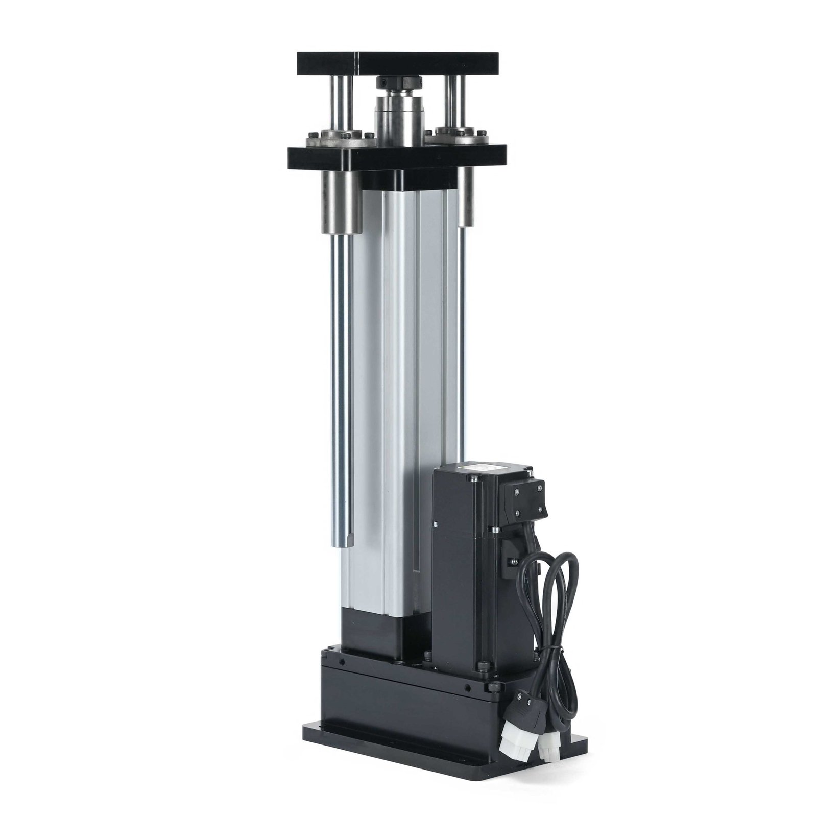
In brief: Servo motor control modes commonly include position, velocity and torque. The drive, controller and machine safety design determine how each mode is implemented.
servo motor control modes: engineering checklist
Define the application requirement and record the baseline before adjusting hardware or controls. Each actuator configuration has model-specific limits, so confirm claims against the selected datasheet, drive manual and machine drawing.
Position control
The controller commands a target position or motion trajectory. Encoder feedback helps the drive track it, but actual tool position can differ because of backlash, compliance and thermal effects. Use position mode for defined stroke endpoints and verify limits and homing.
Velocity control
The controller requests a speed while a higher-level loop or process determines when to stop. This can suit conveying or continuous travel segments. Define stopping distance, acceleration, end limits and fault response so speed control does not imply uncontrolled travel.
Torque control
A torque command regulates motor output within configured limits; it is not automatically a calibrated process-force measurement at the tool. Screw lead, efficiency and friction affect the conversion. For force-critical pressing, use suitable sensing and validation.
Choosing and switching modes
Document the process objective and transition conditions. Test the actual load, following error and safety response. A drive may support all three modes, but the controller interface and selected hardware must be compatible. Consult the drive manual before changing a live production mode.
Practical verification steps
- Record the actuator model, load, stroke, speed, duty, mounting orientation and relevant alarms.
- Compare measurements with the actual component documentation.
- Inspect the mechanical load path, wiring and safety controls before changing settings.
- Change one condition at a time and retest the production cycle.
Frequently asked question
What should be included in a model review? Send the load case, motion profile, environmental conditions and installation drawing. These details support a model-specific recommendation and make assumptions visible.
Explore the NEFEIT resource center, failure diagnosis guide and product range, or contact NEFEIT engineering. The THK technical resources offer linear-motion background; follow the installed components’ manuals for actual requirements.