
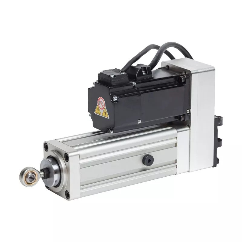
In brief: A servo electric cylinder motor brake may be needed to hold a gravity-loaded axis when power is removed. The machine risk assessment determines the required behavior.
servo electric cylinder motor brake: engineering checks
Use the application drawing, motion profile and exact component manuals. Record the operating baseline before changing settings so that a correction can be verified under the same load and cycle.
Separate holding from stopping
A holding brake is generally intended to keep a stopped axis in position, not to decelerate a moving load. Verify the selected brake’s rated holding torque and duty with the motor manufacturer. Do not treat it as a safety brake without the required design and validation.
Check vertical and inclined axes
Calculate the worst gravity load through the screw and transmission at every operating position. Consider the effect of backlash, coupling failure and loss of drive power. A counterbalance or other safeguard may be required by the machine design.
Coordinate drive logic
Define when the brake releases and engages relative to motor torque, acceleration and stopping. A timing error can cause a drop or brake wear. Confirm wiring, supply voltage and fault response against the drive and brake manuals.
Inspect and verify
Test holding under the approved maintenance procedure and record the load and position. Monitor wear and alarms according to the supplier schedule. Ask a qualified machine safety engineer to review any personnel exposure or suspended load.
What to document
- Actuator, motor and drive models, payload, stroke, orientation and duty cycle.
- Alarm code, current, command and actual position at the first symptom.
- Mechanical alignment, external guidance, travel limits and safety response.
- One controlled change and a repeat test under the full production cycle.
Frequently asked question
Can I use one force or accuracy value for every model? No. Ratings depend on screw, motor, drive, mounting and duty. Ask for the datasheet and a review of the actual load case.
For adjacent topics, see the NEFEIT resource center, selection guide and failure diagnosis. Contact NEFEIT engineering with your drawing and trace data. For general guidance on linear motion components, consult THK technical resources alongside the actual component manuals.