
NFTDP134 High-Frequency Servo Punching Cylinder
An NFTDP134 short-stroke servo punching cylinder configuration for cyclic axial processing. Catalog force options are 80.9 / 107 kN; tooling, material and repetition rate determine the released working duty.
- Short working stroke — 20 mm catalog stroke. Define tooling clearance, actual cut travel and overtravel reserve.
- Configuration-specific force — 80.9 / 107 kN options; do not combine unrelated motor and reducer combinations.
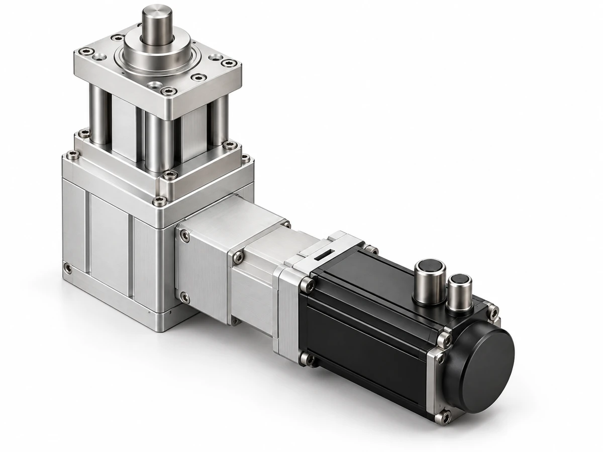
Configuration options
20 mm catalog stroke. Define tooling clearance, actual cut travel and overtravel reserve.
Working cycle
Approach, working movement, dwell and return reviewed together.
Mechanical integration
Mounting, load path and independent guidance defined for your machine.
Engineering support
Drive and feedback selection with NEFEIT.
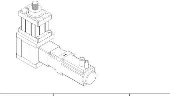
Size the punching process
Specify material, thickness, cutting perimeter, shear strength and tooling condition. Include return resistance and stripping force rather than selecting only from nominal thrust.
- 80.9 / 107 kN options; do not combine unrelated motor and reducer combinations.
- Frequency is a working-cycle reference, not a linear speed in mm/s.
Images show the product layout and installation concept. However, the approved configuration drawing defines the assembly supplied.
Configuration specifications
| Parameter | Catalog reference |
|---|---|
| Stroke | 20 mm |
| Thrust options | 80.9 / 107 kN |
| Motor options | 3000 / 4000 W |
| Motor speed | 3000 rpm |
| Reduction ratio | 10:1 |
| Cycle-frequency reference | 5 Hz |
| Repeat positioning reference | ±0.01 mm; verify measurement conditions |
| Mounting | Front flange plate |
Catalog references apply to the stated configuration. Confirm tooling, sustained duty and calibrated measurement conditions.
Check the drawing for this product configuration
Confirm the mounting, tool interface and full movement envelope for the selected process configuration.
Mechanical drawing
Request flange pattern, body envelope, rod connection and installed length for this configuration.
Tooling support
Provide guide layout, reaction structure and axial alignment requirements.
Utilities and feedback
Confirm motor/drive, sensors, connectors and control responsibilities.
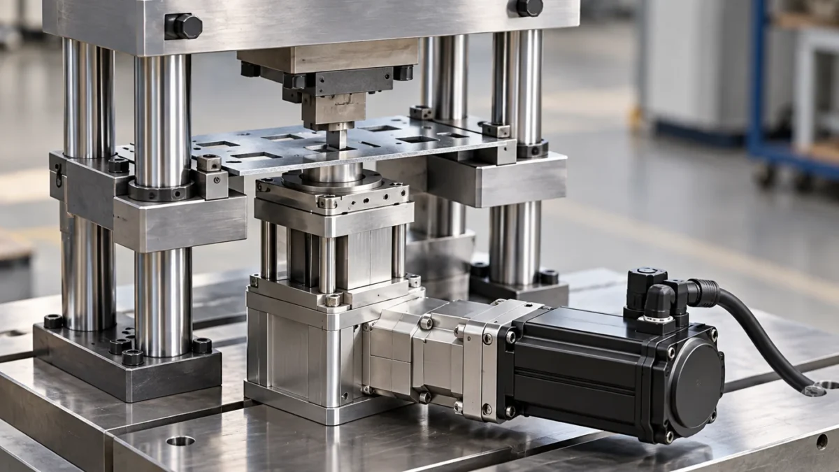
Plate processing: guide the punch through the fixture
A supported steel plate is processed in a guided die within a rigid frame. The actuator supplies the short axial stroke; the tooling system determines alignment, cutting clearance and stripping behavior.
- Review cutting and stripping loads separately
- Define actual cut travel within the 20 mm stroke
- Check frame response at the requested cycle frequency
Provide the inputs that define your configuration
Technical interfaces
Before you design mating parts, review the product drawing and available space with NEFEIT. The approved drawing defines the supplied configuration and mechanical interfaces.
Selection checklist
- Material, thickness, cutting perimeter and shear strength
- Cutting, stripping and return loads
- Required waveform, frequency and operating hours
- Die guidance, reaction frame and flange interfaces
The quotation confirms the mechanical, electrical, feedback and integration scope.
Product selection questions
Catalog references apply to the stated configuration. Confirm tooling, sustained duty and calibrated measurement conditions.
Support the workpiece and guide the tool independently. Review axial alignment, frame stiffness and transverse-load isolation.
Agree calibrated sensor ranges, loaded measurement conditions and trials with the actual parts. Catalog accuracy figures are configuration references.
Confirm the actuator, motor/drive, drawing, feedback, controller and tooling responsibilities for the supplied scope.
Select NFTDP134 for your machine requirements
To request a quotation, send your load, stroke, speed, working cycle and installation drawing. NEFEIT then reviews the motor, feedback and mechanical interfaces with you.