
NFT50 Inline Servo Electric Cylinder
The NFT50 inline electric cylinder uses a ball-screw drive with the servo motor on the cylinder axis. To select a configuration, match the motor, screw lead and mounting to your load, stroke and working cycle.
- Motor arrangement — Motor on the cylinder axis; reserve axial motor clearance.
- Stroke reference — 10–400 mm; final selection includes screw stability and mounting.
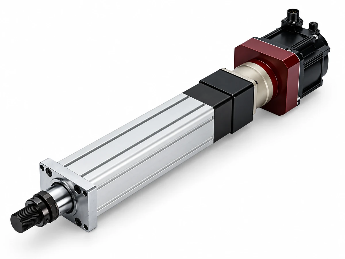
Configuration options
Motor on the cylinder axis; reserve axial motor clearance.
Working cycle
Approach, working movement, dwell and return reviewed together.
Mechanical integration
Mounting, load path and independent guidance defined for your machine.
Engineering support
Drive and feedback selection with NEFEIT.
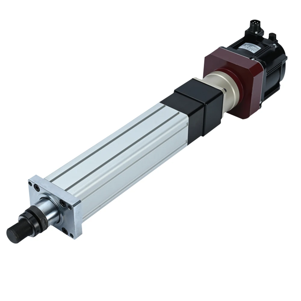
Motor on the axis. Space reserved behind the cylinder.
The coaxial motor arrangement creates a direct axial transmission layout. Allow space for the motor, connectors and service access.
- 10–400 mm; final selection includes screw stability and mounting.
- Choose 4 or 5 mm lead for greater thrust per motor torque; 10 mm lead for faster travel.
Images show the product layout and installation concept. However, the approved configuration drawing defines the assembly supplied.
Select motor, lead, thrust and speed together
| Configuration | Reference |
|---|---|
| Series / arrangement | NFT50 / Inline |
| Reference stroke | 10–400 mm |
| Screw lead | 4 / 5 / 10 mm |
| Motor power | 100 / 200 / 400 W |
| Performance | Reference |
|---|---|
| Base-body capability limit | 1.2 kN |
| Continuous thrust | Use the paired motor/lead rows |
| Mounting interfaces | Drawing-defined |
| Supply scope | Configured quotation |
| Lead (mm) | Motor (W) | Thrust (kN) | Speed (mm/s) | Motor (rpm) |
|---|---|---|---|---|
| 4 | 100 | 0.4 | 200 | 3000 |
| 4 | 200 | 0.8 | 200 | 3000 |
| 4 | 400 | 1.2 | 200 | 3000 |
| 5 | 100 | 0.3 | 250 | 3000 |
| 5 | 200 | 0.65 | 250 | 3000 |
| 5 | 400 | 1.2 | 250 | 3000 |
| 10 | 100 | 0.15 | 500 | 3000 |
| 10 | 200 | 0.3 | 500 | 3000 |
| 10 | 400 | 0.65 | 500 | 3000 |
The body limit is a catalog boundary, not a continuous motor rating. Therefore, use thrust and speed from the same configuration row. Also check the transmission ratio and thermal duty.
Check the drawing for this product configuration
Choose the motor arrangement and mounting separately. For example, FA means front flange, FB means rear flange and LB means side flange. FC identifies a custom interface defined by the drawing.
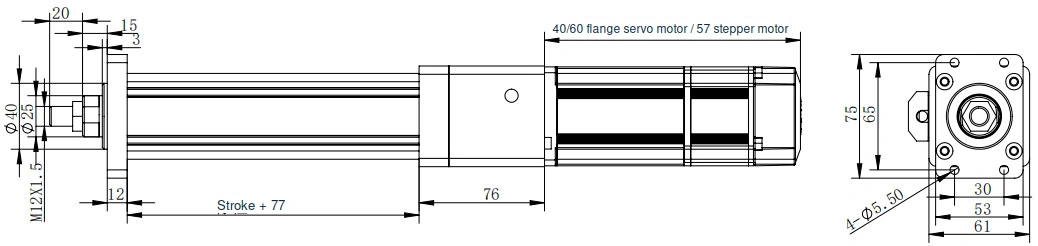
FA — Front flange
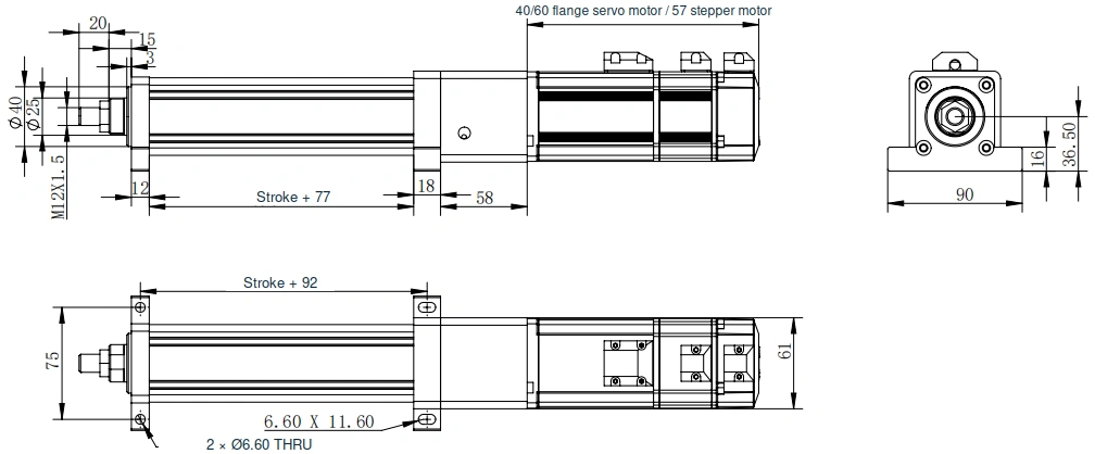
LB — Side flange
Dimensions are in millimetres. Before machining mating parts, confirm the stroke, motor envelope and rod interface. The English drawing retains the source geometry and dimensions.
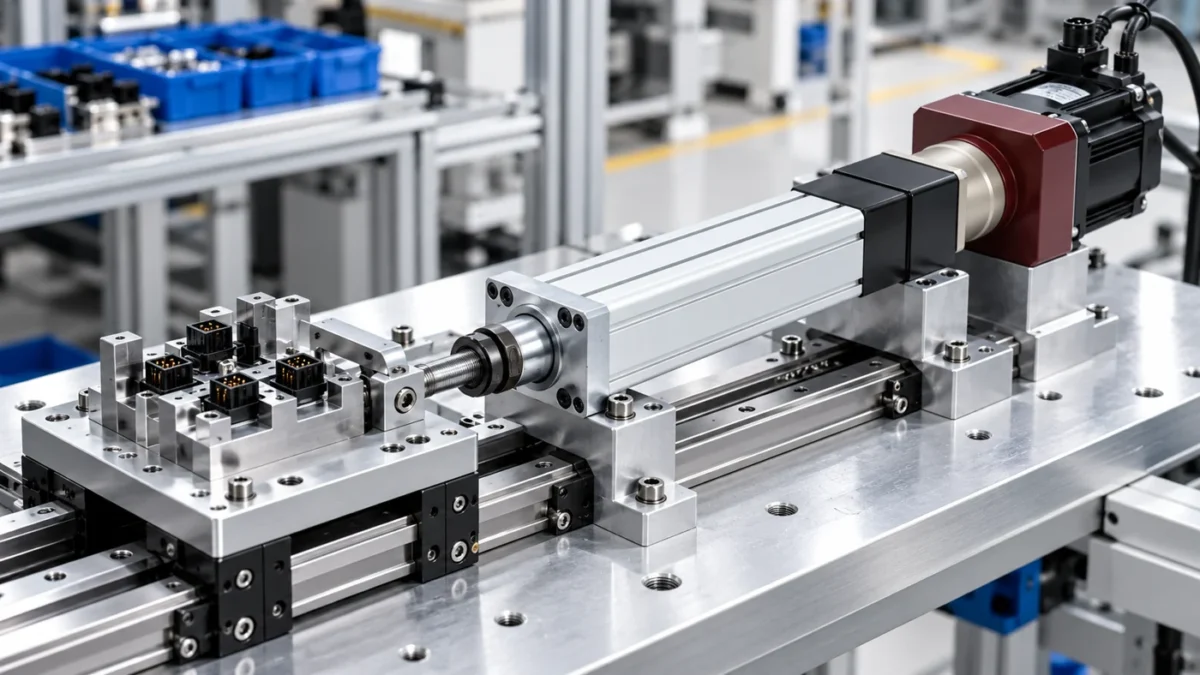
Connector assembly: move a supported locating nest
The inline cylinder positions a guided connector nest beneath assembly tooling. Separate fixture guides carry the workpiece and tooling loads, while the rod supplies axial travel.
- Reference the nest to the connector datum
- Choose lead and motor from one performance row
- Confirm access for tooling and sensor cables
Provide the inputs that define your configuration
Technical interfaces
Before you design mating parts, review the product drawing and available space with NEFEIT. The approved drawing defines the supplied configuration and mechanical interfaces.
Selection checklist
- Working and peak load, orientation and load direction
- Required stroke and approach, working and return speeds
- Cycles per minute, dwell and operating hours
- Mounting envelope, motor/drive and feedback requirements
Order fields: NFT50–stroke–lead–D–mounting–ratio–motor power.
Product selection questions
The body limit describes a catalog capability boundary. Continuous thrust depends on the paired motor, lead, transmission and operating duty.
Inline describes motor placement. Flange or custom mounting is selected independently against the configuration drawing.
The manual associates ±0.01 mm with additional linear feedback. Confirm loaded positioning, repeatability and measurement conditions for the selected system.
The manual describes a non-self-locking ball-screw drive. Review vertical holding, braking and mechanical restraint as part of the complete machine.
Select NFT50 for your machine requirements
To request a quotation, send your load, stroke, speed, working cycle and installation drawing. NEFEIT then reviews the motor, feedback and mechanical interfaces with you.